Introduction
Soil moisture sensors function as critical measurement tools across agriculture, construction, environmental monitoring, and industrial materials processing — with operational decisions frequently driven by real-time moisture data. Precision irrigation scheduling alone affects approximately 13% of US farms, while geotechnical monitoring networks rely on continuous soil moisture readings to predict landslide risk and slope stability.
Despite widespread deployment, the underlying working principles of these sensors are frequently misunderstood. This knowledge gap leads to poor technology selection, avoidable calibration failures, and unreliable data that undermines the very decisions the sensors are supposed to support.
When a sensor's operating frequency, installation method, or calibration approach doesn't match the soil conditions and application requirements, the result is actively misleading data — not merely marginal error.
Key Takeaways
- Soil moisture sensors measure water indirectly using electrical, electromagnetic, or thermal proxies rather than physical extraction
- Commercial sensors exploit water's high dielectric constant (~80 vs. ~4 for soil solids) to infer volumetric water content
- Sensor types — resistive probes, TDR, FDR, and capacitance — each carry distinct accuracy, cost, and application trade-offs
- Performance depends directly on soil type, salinity, temperature, installation technique, and measurement frequency
- Applications span agricultural irrigation, geotechnical monitoring, environmental research, and industrial materials processing
What Is Soil Moisture Sensor Technology?
Soil moisture sensors measure either volumetric water content (VWC) — the amount of water per unit volume of soil — or the energy state of water in soil (matric potential), using proxy physical properties rather than destructive sampling.
They exist to solve a specific operational gap. Direct gravimetric measurement (removing, drying, and weighing soil samples) is destructive and time-intensive, making it incompatible with continuous or real-time monitoring.
These sensors are not atmospheric humidity sensors or dew point meters, which measure water vapour in air. Soil moisture sensors measure water held within a porous solid medium, where the water exists in a complex energy state influenced by surface tension, particle adhesion, and gravity.
Two Fundamental Measurement Paradigms
| Paradigm | What It Measures | Core Question |
|---|---|---|
| Volumetric water content (VWC) | Water as a % of total soil volume (e.g., 25% VWC = 0.25 cm³ water per cm³ soil) | "How much water is here?" |
| Water potential / matric potential | Energy required to extract water from soil particles, in kPa or centibars | "How available is this water to plants or processes?" |
Choosing the wrong paradigm produces data that doesn't support the intended decision — a common and avoidable setup error.
Invasive vs. Non-Invasive Categories
Invasive (contact) sensors require physical insertion into the soil and provide point-scale, high-resolution data at specific depths. Non-invasive sensors operate externally without soil disturbance and are suited for large-area or remote monitoring. Process context and installation constraints typically determine the right category — and that choice shapes every subsequent decision about sensor type, placement, and calibration protocol.
Main Types of Soil Moisture Sensors
Dielectric Sensors (TDR, FDR, and Capacitance)
Dielectric sensors dominate commercial deployment because they exploit a fundamental physical difference: liquid water has a dielectric constant of approximately 80, whilst soil solids measure roughly 4 and air approximately 1. When water content changes, the soil's overall charge-storing capacity changes proportionally, which the sensor detects and converts to VWC.
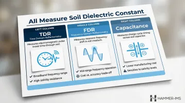
Three variants exploit this same dielectric principle through different mechanisms:
- TDR (Time Domain Reflectometry) measures how long an electromagnetic pulse takes to travel along transmission rods — longer travel time indicates higher dielectric (more water)
- FDR (Frequency Domain Reflectometry) measures the shift in resonant frequency of an oscillating circuit — lower resonant frequency indicates higher dielectric
- Capacitance sensors measure charge-cycle characteristics in a capacitor circuit where soil acts as the dielectric medium
All three measure the same underlying property. They differ in cost, complexity, and susceptibility to interference from soil salinity and temperature.
Resistive Sensors
Resistive sensors represent the lowest-cost option: electrodes inserted into soil allow current to flow, with resistance decreasing as moisture increases. However, accuracy depends on the assumption that ion concentration (soil salinity) remains constant — which it rarely does in real conditions. As METER Group notes, salinity shifts cause resistance readings to change even when water content has not. Research confirms these sensors are unsuitable for applications requiring reliable volumetric data, with errors reaching up to 12.47% in medium-textured soils.
Tensiometers and Matric Potential Sensors
Tensiometers measure the tension (negative pressure) soil exerts on water using a porous ceramic cup and vacuum gauge. Readings are expressed in centibars or kPa. Gypsum blocks and granular matrix sensors infer tension via electrical resistance within a porous medium that equilibrates with surrounding soil.
These sensors answer questions about plant-available water and irrigation trigger points rather than total water volume. Their key limitation is cavitation: tensiometers cannot measure tensions exceeding approximately 75 kPa because air comes out of solution and breaks the water column.
Neutron Probe Technology
Neutron probes emit high-energy neutrons from a radioactive source that slow down upon collision with hydrogen atoms in soil water. The density of slowed neutrons correlates to water content. Whilst highly accurate and unaffected by soil salinity, regulatory requirements for radioactive material handling, licensing costs, and inability to support continuous automated monitoring have driven a marked decline in neutron probe adoption, with operators actively seeking non-nuclear alternatives.
Emerging Non-Invasive Approaches
The regulatory burden and operational constraints of neutron probes have accelerated interest in technologies that require no radioactive materials at all. Microwave-based sensors, ground-penetrating radar (GPR), and cosmic-ray neutron sensing (CRNS) enable large-scale, non-destructive measurement. Microwave energy interacts with dipole water molecules in ways that allow surface and near-surface moisture estimation without probe insertion. CRNS provides area-average soil moisture measurements over a horizontal footprint of 130 to 240 metres in radius, whilst drone-borne GPR systems map root-zone soil moisture down to depths of 35–40 cm without disturbing the crop canopy.
How Do Soil Moisture Sensors Work?
Most sensor types follow the same operational sequence: generate a signal, transmit it through soil, detect how water content alters it, then convert the result into a moisture reading. Accuracy depends on how well each stage performs.
Signal Initiation
Dielectric sensors generate their signals automatically and continuously. Depending on sensor type, the electronics produce one of three signal forms:
- TDR: a high-frequency electromagnetic pulse
- FDR: an oscillating signal swept across a frequency range
- Capacitance: a square-wave excitation applied to a capacitor circuit
Operating frequency matters here. Sensors running above approximately 50 MHz polarise water molecules without also polarising dissolved ions, making them far less sensitive to soil salinity than lower-frequency sensors.
Core Measurement Principle
The sensor places two or more electrodes (probes or rods) in contact with soil and applies its signal. The soil acts as a dielectric medium — the more water present, the higher the dielectric constant, and the more the signal is affected (slowed, shifted in frequency, or altered in charge-time). The sensor electronics measure the magnitude of this change with high precision.
Air gaps between sensor and soil are profoundly damaging. Any gap replaces high-dielectric water-bearing soil with low-dielectric air, causing the sensor to read lower than actual moisture content. This is the single most common cause of systematic underestimation in field deployments.
Calibration and Regulation
Raw sensor output (travel time, frequency, or voltage) converts to VWC through a calibration equation. Factory-supplied generic equations — often based on Topp et al.'s foundational 1980 work — perform adequately across typical mineral soils. Accuracy degrades, however, in soils with high clay content, high organic matter, atypical bulk density, or elevated salinity.
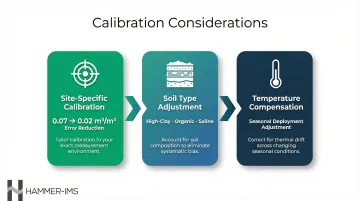
Three calibration considerations are worth addressing before deployment:
- Site-specific calibration: Validating sensor readings against gravimetric measurements in the actual deployment soil reduces typical error from 0.07 m³/m³ to 0.02 m³/m³ — a more than threefold improvement in accuracy. For research-grade applications, this step is not optional.
- Soil type adjustment: Generic equations underperform in high-clay, high-organic-matter, or high-salinity soils; soil-specific coefficients correct for this.
- Temperature compensation: Temperature affects the dielectric properties of both water and soil, so sensors deployed across seasons require compensation adjustments.
Output and Integration
The sensor ultimately delivers a continuous or time-stamped stream of VWC values (typically expressed as a percentage, e.g., 25% VWC = 0.25 cm³ water per cm³ soil) or tension readings (in kPa or centibars). This output feeds downstream decisions:
- Irrigation trigger systems compare VWC against field capacity and management allowable depletion thresholds
- In research and industrial contexts, sensors typically connect to data loggers, IoT platforms, or SCADA systems for real-time visualisation and automated process adjustment
Key Factors Affecting Sensor Performance
Soil-Specific Variables
Soil properties are the primary source of measurement error:
- Texture: Clay vs. sand alters both dielectric behaviour and the proportion of bound vs. free water
- Bulk density: Affects the solid-to-pore ratio and thus dielectric composition
- Salinity/electrical conductivity: Elevated ion concentration causes lower-frequency dielectric sensors to read inflated moisture values
- Clay mineralogy: Shrink-swell clays create contact problems and variable dielectric behaviour
Studies show sensor accuracy changes substantially across soil types without site-specific calibration, with root mean square errors varying from 0 to 0.52 m³/m³ depending on soil conditions.
Installation Quality
Installation quality is equally important and often underestimated:
- Air gaps at the sensor-soil interface are the single most common cause of systematic underestimation
- Soil compaction around sensors during installation artificially elevates readings
- Soil slurry backfill can improve contact but may alter local soil structure
- Horizontal vs. vertical orientation affects which soil volume is being sampled and should match the intended measurement depth
Measurement Frequency and Sensor Design
Sensors operating in the kHz range (common in inexpensive consumer devices) are highly sensitive to dissolved ions and clay charge effects, making them unreliable in any soil with variable salinity or fertiliser inputs. Sensors operating at 50 MHz and above selectively polarise water molecules while avoiding ion polarisation, producing more stable readings across variable soil conditions.
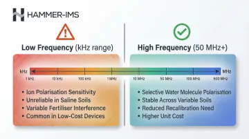
Higher frequency design increases unit cost but reduces the need for recalibration and in-field error correction over time.
Where Soil Moisture Sensors Are Used
Agricultural Irrigation Management
Sensors are installed at multiple depths — typically one-third and two-thirds of the root zone depth — to monitor both water availability and drainage. Data feeds into irrigation scheduling decisions that trigger watering only when soil moisture depletion reaches a management allowable threshold. Transitioning from time-based to sensor-based irrigation scheduling yields water savings averaging 38%, with specific studies showing up to 66.2% reductions in water use on turfgrass.
Geotechnical and Environmental Monitoring
Soil moisture data is critical for:
- Slope stability analysis: Moisture content changes are a leading indicator of landslide risk
- Roadbed integrity monitoring: Prevents subsidence and structural failure
- Landfill management: Controls leachate generation and gas production
- Hydrological research: Validates watershed and climate models
Sensors installed in these applications typically operate continuously and transmit data to remote monitoring platforms, often integrated with alert systems.
Industrial and Materials Processing
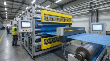
Moisture measurement is a quality-critical parameter in the production of nonwovens, building materials, paper, composite panels, and technical textiles — where material moisture content directly affects downstream processing performance and product specifications. The underlying electromagnetic measurement principles carry over from soil sensing, but industrial lines require contactless, non-nuclear systems capable of operating inline at production speeds.
Hammer-IMS's M-Ray technology applies millimetre-wave electromagnetic signals (30–300 GHz) to measure moisture in moving materials without contact or radioactive components. This approach enables real-time process adjustment and material waste reduction directly on the production line.
Conclusion
Every sensor type — from a simple resistance probe to a research-grade TDR system — works by exploiting a measurable physical property of water and converting that property to a moisture value through calibration. Water's resistance to current flow, its charge-storing capacity, or its interaction with electromagnetic signals provides the measurement foundation.
The physical mechanism a sensor uses directly determines how it behaves under variable soil, salinity, and temperature conditions. That's why accuracy requires more than simply inserting a probe into the ground.
Whether the application is managing irrigation thresholds, monitoring geotechnical risk, or controlling moisture-sensitive industrial processes, decisions from sensor data are only as good as the measurement principle behind them. Deployment method and site-appropriate calibration matter just as much as the hardware itself. Organisations that treat sensor selection as a technical decision — rather than a procurement shortcut — consistently get data they can actually act on.
Frequently Asked Questions
What is the difference between a volumetric water content sensor and a soil water potential sensor?
VWC sensors measure how much water is present as a percentage of soil volume, whilst water potential sensors measure the energy state or tension of that water — the force soil exerts on water molecules. In short: VWC quantifies water present; water potential indicates how available that water is to plants or processes.
Why are resistance-based soil moisture sensors considered unreliable for accurate measurement?
Resistance sensors assume constant ion concentration in soil pore water, but salinity and fertiliser levels vary. When ion concentration changes, resistance changes even if water content has not, making it impossible to distinguish moisture change from salinity change without separate calibration for every soil condition.
How often do soil moisture sensors need to be recalibrated?
Factory calibration is adequate for typical mineral soils, but sensors deployed in clay-rich, organic, or saline soils should be validated against gravimetric sampling at the start of each deployment season. Recalibration is also recommended after significant soil disturbance or when sensors are moved to a different soil type.
What role does the dielectric constant play in soil moisture measurement?
The dielectric constant measures a material's ability to store electrical charge. Water's value is approximately 80, compared to roughly 4 for soil solids and 1 for air — so even small changes in water content produce a measurable shift in the soil's overall dielectric constant that sensors can detect and convert to volumetric water content.
Can soil moisture sensors be used accurately in saline or high-clay soils?
Performance depends heavily on measurement frequency — sensors operating below 50 MHz are vulnerable to electrical conductivity and clay charge effects. TDR sensors handle saline conditions better due to their broadband frequency range, whilst high-frequency capacitance sensors can also perform adequately with site-specific calibration.
What is the key operational difference between TDR and FDR soil moisture sensors?
TDR sensors measure the travel time of a reflected electromagnetic pulse along transmission rods; longer travel time indicates higher dielectric and more water. FDR sensors apply an oscillating signal and measure the resulting resonant frequency shift — a lower frequency indicates higher dielectric. TDR handles salinity better due to its broadband signal, but is more complex and costly than FDR.