Introduction
Getting plating thickness wrong carries steep consequences. Undersized plating leads to corrosion failure, premature wear, and rejected parts. Oversized plating wastes expensive materials like gold, nickel, or zinc—sometimes by hundreds of kilograms per month in high-volume operations. For manufacturers, measurement accuracy directly determines product reliability and the cost of rework.
Choosing the right measurement method is where things get complicated. Each technique suits specific material combinations, substrate types, and production environments.
X-ray fluorescence delivers precision for multilayer gold plating on circuit boards, but it's overkill for zinc coatings on steel bolts. Eddy current works brilliantly on anodised aluminium but fails when both coating and substrate are conductive.
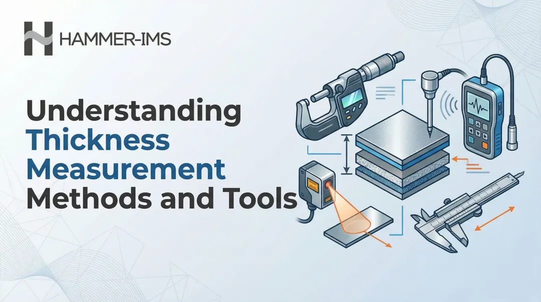
This article breaks down the five main plating thickness measurement techniques: X-ray Fluorescence (XRF), Eddy Current, Magnetic Induction, Beta Backscatter, and Mechanical Cross-Sectioning. You'll learn how each method works, when to use it, and how to match technique to application.
Key Takeaways
- Accurate plating thickness measurement prevents costly rework and rejects by confirming coatings meet spec
- Five main techniques: XRF, Eddy Current, Magnetic Induction, Beta Backscatter, and Cross-Sectioning
- Non-destructive methods preserve parts intact; destructive methods are used for validation or failure analysis
- Method selection depends on coating material, substrate type, accuracy requirements, and part geometry
- Inline monitoring systems track thickness continuously, allowing real-time process corrections before defects occur
What Is Plating Thickness Measurement — and Why It Matters
Plating thickness measurement quantifies the depth of a deposited metal coating on a substrate. Thickness is typically expressed in micrometres (µm), microinches (µin), or mils (thousandths of an inch), depending on the industry standard. For reference: 1 µm equals approximately 39 µin, and 1 mil equals 25.4 µm.
Functional Consequences of Incorrect Thickness
Getting thickness wrong in either direction carries real costs:
| Scenario | Consequence |
|---|---|
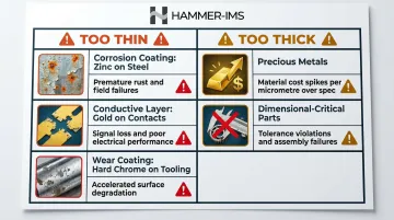
| Too thin — corrosion coating (zinc on steel) | Premature rust, field failures |
| Too thin — conductive layer (gold on contacts) | Signal loss, poor electrical performance |
| Too thin — wear coating (hard chrome on tooling) | Accelerated surface degradation |
| Too thick — any precious metal (gold, palladium) | Material costs spike with every micrometre over spec |
| Too thick — dimensional-critical parts | Tolerance violations; parts won't fit assemblies |
Controlling thickness precisely is, in practical terms, a direct lever on both product quality and production economics.
Where Thickness Measurement Is Required
Measurement checkpoints span the entire production cycle:
- Process setup validation before production runs
- Quality control inspection during production
- Incoming inspection of plated components from suppliers
- Failure analysis when parts don't meet performance standards
- Compliance verification against ASTM, MIL-specs, and IPC standards
The Main Plating Thickness Measurement Techniques
The primary classification that drives technique selection is simple: destructive vs. non-destructive. Destructive methods damage or alter the sample; non-destructive methods preserve the part for use.
Most industrial applications favour non-destructive approaches — a part destroyed during inspection can't be shipped. Destructive methods remain essential for detailed cross-sectional analysis and calibration verification.
No single method works across all coating/substrate combinations. The choice depends on three factors: the materials involved, the thickness range, and part geometry. The five methods below cover the full spectrum from routine production QC to forensic failure analysis.
X-Ray Fluorescence (XRF)
XRF bombards the coating with X-rays, exciting atoms in the plating to emit fluorescent X-rays at energy levels characteristic of each element. A detector measures the intensity of this fluorescence, which correlates to coating thickness.
Key strengths:
- Non-destructive and non-contact
- Fast measurement of small or complex parts
- Capable of multilayer analysis (e.g., Ni/Pd/Au on Cu)
- Elemental identification alongside thickness measurement
Limitations:
- Measurement errors when plating and substrate have similar atomic numbers
- Sensitive to film density and purity
- Higher equipment cost compared to probe-based methods
Best for: Precious metal plating, multilayer coatings on electronics, applications requiring elemental verification.
Eddy Current Method
An alternating current in a probe induces eddy currents in the conductive substrate beneath the coating. The distance between the probe and substrate—the coating thickness—affects the magnitude of the eddy current and reflected impedance, which is measured and converted to thickness.
Key application window:
- Non-conductive coatings on non-ferrous metal substrates
- Examples: anodising on aluminium, paint on copper, polymer coatings on brass
Limitations:
- Sensitive to surface roughness, part curvature, and substrate conductivity variations
- Not suitable when both coating and substrate are conductive
- Requires relatively flat or consistently curved surfaces
Best for: Anodised aluminium parts, polymer-coated electronics, paint on non-ferrous metals.
Magnetic Induction Method
A probe acts as part of a transformer circuit. The presence of a ferromagnetic substrate increases magnetic flux and output voltage in proportion to how close the probe is to the substrate surface. This distance—the coating thickness—is measured based on the change in magnetic field strength.
Key application domain:
- Non-magnetic coatings on ferromagnetic substrates (steel, iron)
- Examples: zinc, cadmium, chrome, paint, or powder coating on steel
Limitations:
- Not applicable when the substrate is non-magnetic
- Surface roughness and substrate thickness can affect readings
- Requires calibration for specific substrate material properties
Best for: Galvanised steel, painted structural steel, chrome-plated fasteners, powder-coated metal fabrications.
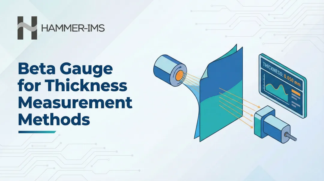
Beta Backscatter Method
A radioactive source emits beta particles (electrons) that penetrate the coating and scatter back from the substrate. A Geiger-Mueller tube counts the backscattered particles. Since the count rate changes with coating thickness and the density difference between coating and substrate, thickness can be calculated.
This method requires a density difference of at least 20% between coating and substrate, which makes it well-suited for precious metal plating — gold on nickel, tin-lead on copper, titanium nitride on steel.
The significant practical constraint is the radioactive source. Regulatory compliance, storage protocols, and safety requirements add operational overhead that XRF-based systems avoid. Most new installations prefer XRF for equivalent applications.
Best for: Facilities with existing beta backscatter equipment, or applications with well-matched density differentials and no viable XRF alternative.
Mechanical Cross-Sectioning
Sample preparation follows a fixed sequence: cut, embed in resin, lap, polish, and etch to expose the plating layers. The cross-section is then measured under a microscope. For nanometre-scale multilayer analysis, focused ion beam scanning electron microscopy (FIB-SEM) is used.
When this method is appropriate:
- Validation or failure analysis rather than routine production measurement
- Direct visual confirmation of layer structure, interface adhesion, and defects (voids, pinholes)
- Cross-referencing with non-destructive methods like XRF to verify accuracy, especially for multilayer coatings
Limitations:
- Destructive—part cannot be used
- Time-consuming sample preparation
- Not suitable for high-volume production QC
Best for: Process qualification, root cause failure analysis, calibration verification.
How to Choose the Right Measurement Technique for Your Application
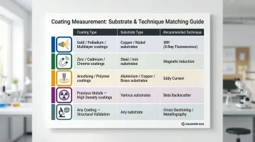
Match Technique to Coating and Substrate Compatibility
| Coating Type | Substrate Type | Recommended Technique |
|---|---|---|
| Gold, palladium, multilayer precious metals | Copper, nickel | XRF |
| Zinc, cadmium, chrome | Steel, iron | Magnetic Induction |
| Anodising, polymer coatings | Aluminium, copper, brass | Eddy Current |
| Precious metals with high density differential | Various | Beta Backscatter (legacy) |
| Any coating requiring structural validation | Any substrate | Cross-Sectioning (destructive) |
Destructive vs. Non-Destructive Decision Point
Non-destructive methods (XRF, eddy current, magnetic induction, beta backscatter) are standard for production QC where parts must be preserved. They allow measurement without altering the component.
Destructive cross-sectioning is reserved for:
- Process validation before production ramp
- New product qualification
- Failure investigation when non-destructive data is insufficient
Don't conflate routine measurement with analytical testing. Cross-sectioning provides the definitive answer, but only when you can afford to sacrifice the part.
Accuracy and Precision Requirements
Measurement precision varies by technique:
- XRF: Most precise method, capable of achieving relative standard deviations below 2–3%, ideal for thin precious metal coatings or multilayer analysis
- Magnetic induction and eddy current: Fast and cost-effective for single-layer coatings in production environments, but with wider tolerance bands (typically ±10%)
- Cross-sectioning: Direct measurement under microscopy, highly accurate but time-intensive
Choose based on the criticality of your application. Aerospace or medical device plating may demand XRF precision; architectural steel coatings may tolerate magnetic induction's wider tolerances.
Part Geometry and Size Constraints
Technique accessibility depends on part shape:
- XRF: Can be tightly focused for measuring microscopic areas on small components (contact points, connector pins)
- Magnetic induction and eddy current: Require flat or consistently curved surfaces; struggle with blind holes, recesses, or sharp edges
- Cross-sectioning: Geometry-agnostic but destructive
Complex geometries limit access for probe-based methods. If your parts have deep recesses or intricate contours, XRF's non-contact measurement may be the only practical option.
Inline vs. Offline Measurement
Most traditional techniques are offline spot-checks on sampled parts. This approach only catches defects after production, when material has already been wasted.
For continuous production lines—coated steel strip, foil, or plated web materials—inline measurement systems monitor thickness across the full material width in real time. This enables:
- Catching deviations while production can still be adjusted
- Automatic process correction through closed-loop feedback
- Reduced material over-use by staying precisely within specification limits
The practical result: fewer scrapped batches, tighter coating tolerances, and less material consumed per metre of output.
How Hammer-IMS Supports Modern Plating Thickness Control
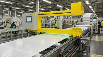
Hammer-IMS provides non-nuclear, contactless inline thickness measurement systems using M-Ray technology (millimetre wave-based). This approach is designed for real-time, continuous measurement in production environments—a modern alternative to offline spot-checking or nuclear-source-based methods.
Real-Time Measurement for Continuous Processes
For manufacturers running continuous plating or coating processes on web or strip materials, the M-Ray sensor measures across the full material width without contact. Real-time thickness data feeds directly into closed-loop production control, allowing automatic process adjustments to maintain spec tolerances and cut material over-use.
Safety and Sustainability
Unlike beta backscatter systems that rely on radioactive isotopes, Hammer-IMS M-Ray technology is non-nuclear and non-radioactive. This eliminates:
- Regulatory burden and licensing complexity
- Isotope handling and storage requirements
- Radiation safety risks for operators
- Disposal and compliance costs
For facilities pursuing cleaner production standards, removing radioactive sources also simplifies site certification and reduces ongoing compliance overhead.
Conclusion
Selecting the right plating thickness measurement technique isn't one-size-fits-all. Success requires matching the method to the coating material, substrate, part geometry, required accuracy, and whether the goal is offline quality verification or real-time production control.
Across industries, the pressure to tighten tolerances, control material costs, and meet sustainability targets is pushing manufacturers toward non-destructive, non-nuclear, and inline measurement approaches. Choosing the right method from the start prevents costly rework, reduces material waste, and keeps production economics working in your favor.
Frequently Asked Questions
Frequently Asked Questions
How to calculate plating thickness?
Plating thickness is typically measured directly using instrumental methods (XRF, eddy current, magnetic induction) rather than calculated. However, it can be estimated using Faraday's Law from electroplating process parameters (current density, time, plating efficiency). Direct measurement is preferred for accuracy in production and quality control contexts.
What is the unit of measurement for plating thickness?
Plating thickness is most commonly expressed in micrometres (µm) or microinches (µin), with some specifications using mils (thousandths of an inch). Standard conversions: 1 µm ≈ 39 µin; 1 mil = 25.4 µm. Different industry standards use different units.
What is the 80/20 rule for DFT measurement?
Per ISO 19840:2012, 80% of individual DFT readings must meet or exceed the specified minimum, and 100% must reach at least 80% of that minimum. This rule applies to protective paint systems on steel structures — not to precision metallic electroplating.
Which plating thickness measurement method is most accurate?
X-ray Fluorescence (XRF) is generally the most precise method, achieving relative standard deviations below 2–3% for thin and multilayer coatings. That said, accuracy still depends on correct calibration, suitable reference standards, and a good match between the method and the coating/substrate system.
What is the difference between destructive and non-destructive plating thickness measurement?
Non-destructive methods (XRF, eddy current, magnetic induction, beta backscatter) measure thickness without damaging the part, making them suitable for production QC on usable components. Destructive methods (cross-sectioning) permanently alter the sample and are used for detailed structural validation, failure analysis, or calibration verification.
Can plating thickness be measured inline during production?
Yes, inline measurement is possible and increasingly adopted for continuous production processes (e.g., coated strip, foil, or web materials). Contactless sensor technologies monitor thickness in real time across the full material width, enabling immediate process feedback rather than relying on post-production sampling.