Introduction
In industrial manufacturing, a deviation of just a few dozen micrometers can mean the difference between a product that performs flawlessly and one that fails under load. Coating thickness errors drive 8–15% of industrial projects into costly rework, while structural thickness failures in pipelines and pressure vessels trigger warranty claims, unplanned downtime, and in extreme cases, safety incidents. Yet thickness measurement remains one of the most misunderstood aspects of process control.
Most measurement errors trace back to method selection, not operator error. A contact gauge that works perfectly on rigid steel will compress and distort soft foam, producing readings that are both inaccurate and damaging. An electromagnetic sensor calibrated for smooth aluminum will deliver false readings on rough, curved substrates.
This guide covers every major thickness measurement method, what each is suited for, and a decision framework for selecting the right tool before errors occur.
TLDR
- Thickness measurement applies to bulk materials (pipe walls, plastic sheets) and thin coatings (paint, plating) alike.
- Key methods span contact tools (calipers, micrometers), electromagnetic gauges, ultrasonic testers, and non-contact systems like optical profilers and millimeter wave sensors.
- Method selection depends on material type, precision needs, access (single vs. dual side), and inline vs. offline use.
- Non-contact methods protect soft or fast-moving materials from deformation and support real-time closed-loop process control.
- Calibration against traceable reference standards is mandatory for compliance and accuracy, regardless of method.
What Is Thickness Measurement — and Why It Matters in Manufacturing
Thickness measurement is the determination of the perpendicular distance between two parallel surfaces of an object. This definition applies both to a material's bulk dimension—such as a pipe wall, steel plate, or extruded plastic sheet—and to thin layers applied to a surface, including paint, plating, or polymer film coatings.
The field divides into two main measurement categories: bulk or structural thickness (typically measured in millimetres) and coating or film thickness, often called Dry Film Thickness (DFT), measured in micrometres (µm) or mils (one-thousandth of an inch). Unit selection matters: industrial coatings and battery films reference µm, while North American plastics and label industries commonly use mils.
Why Accurate Thickness Measurement Matters
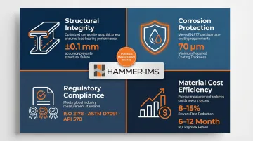
Precise thickness measurement directly influences four critical manufacturing outcomes:
- Structural integrity — Under-thickness pipe walls reduce failure pressure and shorten service life. Optimising composite wrap repair thickness (8.4 mm instead of 16.1 mm) can sustain designed failure pressures while cutting repair costs.
- Corrosion protection performance — EN 877 requires a minimum epoxy coating thickness of 70 µm for 20-year durability in C4 corrosive environments. Insufficient coating leads to premature failure, warranty claims, and equipment downtime.
- Regulatory and standards compliance — Industries mandate specific measurement standards (ISO 2178, ASTM D7091, API 570) to ensure safety, quality, and traceability.
- Material cost efficiency — Thickness failures drive coating rework on 8–15% of projects. Inline closed-loop control cuts material give-away by 1–2% with payback periods of 6–12 months; in blow moulding, consistent wall distribution can reduce material usage by up to 5%.
In aluminium rolling and extrusion, gauge variation defects like "over gauge" generate measurable scrap and rework costs — losses that the right measurement method can prevent. The sections below break down which methods apply to which materials, and how to select the right tool for your process.
Thickness Measurement Methods and Tools: From Contact to Advanced Non-Contact
No single measurement method suits every application. The right choice depends on material properties, substrate type, required precision, and whether measurement occurs in a laboratory, during spot checks, or inline on an active production line.
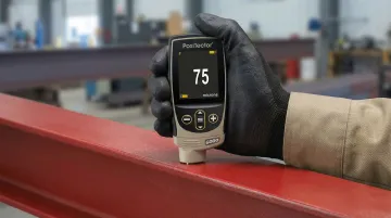
Contact Methods: Calipers, Micrometers, and Dial Gauges
Contact methods work by physically touching the material surface with a probe or jaw and measuring displacement directly. The three common tool types span a wide accuracy range:
- Calipers: Resolution 0.01–0.02 mm, accuracy ±0.02–0.05 mm
- Micrometers: Resolution as fine as 1 µm (0.001 mm), accuracy ±1–3 µm
- Dial and digital thickness gauges: Resolution 0.01–0.001 mm, accuracy ±3–20 µm
Contact methods require calibration using certified gauge blocks traceable to national metrology institutes such as NIST. Mechanical comparisons correct for deformation when materials differ.
Key Limitations:
Physical contact risks deforming soft, compressible, or delicate materials — foam, textiles, and thin polymer films are all vulnerable. ASTM D1777 notes that apparent textile thickness varies inversely with applied pressure, making pressure specification essential; ISO 5084 mandates a specified measuring pressure (for example, 1 kPa). Contact gauges are also unsuitable for moving materials on live production lines.
Electromagnetic Methods: Magnetic Induction and Eddy Current
Electromagnetic gauges measure coating thickness through field interaction without physical damage. Two primary types exist:
- Magnetic induction gauges: For non-magnetic coatings on ferrous (steel) substrates.
- Eddy current gauges: For non-conductive coatings on non-ferrous metals like aluminium.
ASTM D7091 governs nondestructive measurement of dry film thickness using these methods. Typical systems (for example, DeFelsko PosiTector 6000, Elcometer 456) offer ranges of 0–1,500 µm with accuracy of ±1–3% or ±2.5 µm.
Critical Dependencies:
Surface roughness, curvature, and magnetic characteristics all affect readings. Surface profile causes magnetic gauges to overstate true coating thickness. ASTM D7091 and SSPC-PA 2 recommend calculating a base metal reading (BMR) on the bare substrate to subtract from future readings. Strong curvatures (convex diameters <50 mm) require corrective calibrations with customer-specific standards.
Ultrasonic Thickness Measurement (UTM)
Ultrasonic thickness measurement uses a transducer to send high-frequency sound pulses into a material, timing how long each pulse takes to reflect from the back wall and calculating thickness from the material's known sound velocity. ASTM E797/E797M is the governing standard.
Capabilities and Applications:
- Single-side access: Requires access to only one face of the material.
- Resolution: 0.001 mm (high-resolution mode), range 0.08–635 mm (Olympus 38DL PLUS).
- Applications: Pipe wall corrosion monitoring, pressure vessel inspection, and structural components in metals, plastics, and composites.
- Corrosion monitoring compliance: API 570 Piping Inspection Code mandates defined thickness measurement locations (TMLs) for periodic inspections to calculate corrosion rates.
Limitations:
UTM requires couplant gel to provide acoustic coupling. It is unsuitable for very thin films (typically below 0.5 mm without high-frequency delay line transducers) and not ideal for soft or moving materials.
Advanced Non-Contact Methods: Optical, Laser, and Millimeter Wave
Non-contact methods measure remotely, making them the only viable option for delicate, compressible, or fast-moving materials.
Optical and Laser Methods:
- White light interferometry (WLI): Sub-nanometre repeatability (0.08 nm), used for semiconductor wafers, precision optics, and super-smooth surfaces. Sensitive to vibrations and struggles with very rough samples or steep angles.
- Laser triangulation: 0.005 µm repeatability, 30 nm resolution, sampling rates up to 392 kHz (KEYENCE LK-G5000 series). Suited for high-speed inline profiling, battery cell slurry coating, and transparent material applications. Tracking errors can occur on patterned glass or varying reflectance surfaces.
Where optical methods require line-of-sight and surface reflectance consistency, millimeter wave technology takes a different approach — one suited to porous, fibrous, and multi-layer materials that scatter or absorb light.
Millimeter Wave (M-Ray) Technology:
M-Ray systems use electromagnetic waves in the 30–300 GHz range via Frequency Modulated Continuous Wave (FMCW) radar-like operation. The sensor transmits millimeter waves that slow as they pass through the material; the receiver records the time delay as a direct measure of basis weight and thickness.
Capabilities:
- Contactless, non-nuclear measurement with micrometre accuracy.
- High standoff distances (up to 30 cm) and measurement rates exceeding 3 kHz.
- Can resolve multilayer thicknesses down to approximately 6% of the Rayleigh resolution limit.
- Suitable for plastics, textiles, nonwovens, synthetic foams, mineral wools, and rubber.
M-Ray technology is deployed in nonwoven and coated textile plants (Orfit Industries, Heimbach, Grandeco, Vetex) as a clean alternative to nuclear gauges.
How to Choose the Right Thickness Measurement Method for Your Application
Selecting the right method starts with understanding your material and environment, then mapping precision and access requirements to method capabilities.
Start with the Material Substrate
Is it a magnetic metal (steel), non-magnetic metal (aluminium), non-conductive material (plastic, foam, textile), or transparent film?
- Ferrous metals: Magnetic induction gauges work for coatings on steel.
- Non-ferrous metals: Eddy current gauges suit aluminium substrates.
- Non-conductive materials: Ultrasonic and millimeter wave (M-Ray) work across plastics, foams, textiles.
- Transparent films: Optical methods (white light interferometry, laser triangulation) excel.
Address Access and Environment Constraints
Can you reach both sides of the material, or do you need single-side access? Is measurement happening on stationary or moving material?
- Dual-side access: Contact methods (calipers, micrometers) are viable for stationary, rigid materials.
- Single-side access: Ultrasonic and electromagnetic methods measure from one side only.
- Live production lines: Non-contact methods (laser, M-Ray) provide continuous, real-time readings without physical interference or deformation.
Map Precision Requirements to Method
What level of precision does your application demand?
- Sub-micrometre films (optics, electronics): White light interferometry.
- Structural pipe walls (millimetres): Ultrasonic or contact tools.
- Continuous sheet and film production (µm-level precision at line speeds): M-Ray and advanced non-contact systems.
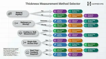
Use a Practical Decision-Making Checklist
| Question | Answer Points to Method |
|---|---|
| Is the material rigid or compressible? | Compressible → non-contact required |
| Is it stationary or moving? | Moving → non-contact required |
| Is coating or bulk thickness being measured? | Coating → electromagnetic or optical; Bulk → ultrasonic or contact |
| Is one-side access the only option? | Yes → ultrasonic, electromagnetic, or optical |
| Is inline/real-time feedback required? | Yes → non-contact (laser, M-Ray) |
Align with Calibration and Standards Requirements
Different industries mandate specific standards that may prescribe or restrict which methods are accepted for compliance purposes:
- ISO 2178: Magnetic method for non-magnetisable coatings on magnetisable base metals.
- ASTM D7091: Nondestructive DFT measurement on ferrous and non-ferrous metals.
- API 570: Piping inspection code heavily referencing UTM for corrosion monitoring.
- ASTM D6988, ISO 4593: Plastic film thickness determination.
- ISO 5084: Textile thickness under specified pressure.
Thickness Measurement in Practice: Managing Quality on a Production Line
Applying thickness measurement inline transforms it from a retrospective quality check into a real-time process control tool. Here's how to implement it effectively.
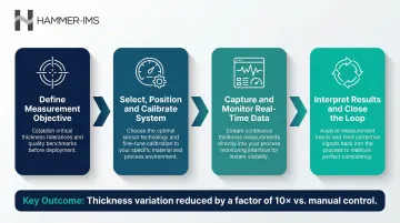
Step 1 – Define the Measurement Objective
Clarify what you're measuring: bulk sheet thickness, coating layer, or multilayer stack. Establish the target specification range and tolerance band. Identify the downstream consequence if thickness drifts out of spec—whether it's coating failure, structural weakness, regulatory non-compliance, or material waste.
Step 2 – Select, Position, and Calibrate the Measurement System
Choose the method appropriate to your material and line speed. Position the gauge or sensor at the correct point in the production flow:
- Inline at the die exit (extrusion)
- Post-curing (coatings)
- End-of-line (final product)
Perform reference calibration using certified standards representative of the actual material being run. For electromagnetic gauges, calculate base metal readings on bare substrate to compensate for roughness. For ultrasonic systems, verify sound velocity for the specific material.
Step 3 – Capture and Monitor Thickness Data in Real Time
Periodic spot-checks — manual readings at fixed intervals — are the traditional approach. The problem: by the time a deviation is detected in the lab, significant off-spec production has already occurred.
Continuous inline measurement uses sensor arrays scanning the full material width at line speed. Multi-head systems such as Hammer-IMS M-Ray scanners enable high material coverage and 2D cross-web profile views, detecting edge-to-edge variations that spot checks miss. In one documented case, roll-to-roll weight variance dropped from ±25 lbs to ±5 lbs after switching to automatic profile control.
Step 4 – Interpret Results and Close the Loop
Thickness data feeds back into process control systems via protocols like Modbus TCP/IP, OPC UA, or PROFINET. This enables automatic adjustments to:
- Thermoelectric or piezo die bolts for plastic sheet extrusion
- Dual-axis coating knives or doctor blades
- Calender roll gaps
Automatic profile control systems compensate for nominal value deviations exactly in the segment of the extrusion die where they occur, reducing thickness variations by a factor of 10 compared to manual control.
Closed-loop inline measurement prevents defects during production rather than discovering them afterward — cutting material waste, tightening thickness margins, and improving overall uptime.
How Hammer-IMS Can Help with Inline Thickness Measurement
Hammer-IMS specialises in non-nuclear, contactless thickness measurement solutions for industrial production lines. Their M-Ray technology uses millimeter wave-based measurement (30–300 GHz) to deliver precise, real-time thickness and basis-weight data without physical contact—making it safe for delicate, compressible, or fast-moving materials that would be deformed or damaged by conventional gauges.
Three capabilities set M-Ray systems apart for inline applications:
- Eliminates material deformation on soft substrates — textiles, nonwovens, foam, and plastic films — because measurement is fully contactless.
- Removes the regulatory burden tied to nuclear-source gauges; in Belgium, FANC will deny nuclear licences when non-nuclear alternatives perform equivalently or better.
- Delivers uniform full-width coverage across the web, producing 2D cross-web profile views that catch anomalies single-point checks miss.
Hammer-IMS's Connectivity 3.0 software enables closed-loop integration: real-time thickness data feeds directly to production control systems, enabling automatic process adjustments that reduce material waste, tighten production thickness margins, and support data logging for quality assurance.
Those capabilities have made Hammer-IMS a trusted partner for manufacturers including Owens Corning, Balta, and Autoneum — operating across plastic sheet extrusion, nonwovens, coated textiles, and automotive insulation.
Conclusion
Thickness measurement method selection is not one-size-fits-all—it depends on substrate, precision needs, access constraints, and whether measurement is inline or offline. Mastering this decision separates reactive quality inspection from proactive process control.
For manufacturers running continuous production of flexible, soft, or non-metallic materials, advanced non-contact inline measurement has become the practical standard for producers who need real-time control, not after-the-fact correction. Evaluate your current measurement setup against the criteria covered in this guide: material compatibility, access requirements, precision demands, and closed-loop control capability. The right method tightens tolerances, cuts scrap rates, and keeps production margins where they need to be — and systems like those from Hammer-IMS are built specifically for that kind of continuous, non-contact inline control.
Frequently Asked Questions
What is the unit of thickness?
Thickness is commonly measured in millimetres (mm) for structural components, micrometres (µm) for thin coatings and films, and mils (one-thousandth of an inch) in imperial-system industries. The appropriate unit depends on the scale and industry context of the measurement.
How thick is 3 mil?
3 mil equals 0.003 inches, or approximately 76.2 micrometres (µm). "Mil" is commonly used in the US coatings, plastics film, and labelling industries to describe thin material or coating thicknesses.
What dimension is thickness?
Thickness is the third linear dimension of an object—typically the smallest—measured perpendicular to the two larger dimensions (length and width). It describes the distance between two opposite parallel surfaces.
What is the difference between contact and non-contact thickness measurement?
Contact methods (calipers, micrometers, ultrasonic with couplant) physically touch the surface, making them unsuitable for soft, delicate, or moving materials. Non-contact methods (electromagnetic gauges, optical sensors, M-Ray) measure remotely and are essential for production-line applications and compressible materials.
What thickness measurement method is best for soft or compressible materials like foam or textiles?
Contact methods deform soft materials, introducing measurement error. Non-contact methods—particularly millimetre wave (M-Ray) or optical non-contact systems—are preferred for foam, textiles, and nonwovens to achieve accurate, deformation-free thickness readings.
How does inline thickness measurement improve production quality and reduce waste?
Inline measurement provides continuous, real-time data across the full material width, enabling immediate process corrections (closed-loop control) rather than catching defects after the fact. This reduces material over-use, tightens thickness margins, and cuts waste—with typical payback periods of 6–12 months.