This guide covers the right tools, the three primary measurement methods, a step-by-step procedure, how to interpret readings, and the most common mistakes to avoid.
Key Takeaways
- Match your method to your material: magnetic induction for steel, eddy current for aluminium, ultrasonic for plastics
- Calibrate your gauge before every use and re-check after battery changes, temperature shifts, or substrate changes
- Factory automotive paint typically measures 100–180 microns; industrial coatings vary by corrosivity class (120–320+ microns for ISO 12944 compliance)
- Inline non-contact systems deliver real-time feedback that spot-check gauges cannot match in production
What You Need to Measure Paint Thickness Accurately
Wrong tool selection and poor surface conditions are the two most common causes of inaccurate readings. Getting both right before you start determines whether your measurements are usable.
Tools and Gauges Required
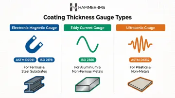
The three main gauge types used across industries are:
- Electronic magnetic gauges – For ferrous/steel substrates, governed by ASTM D7091 and ISO 2178
- Eddy current gauges – For aluminium and non-ferrous metals, governed by ISO 2360
- Ultrasonic gauges – For plastic, fibreglass, and non-metal substrates, governed by ASTM D6132
Combo gauges auto-switch between magnetic and eddy current modes and are common in mixed-substrate environments like automotive assembly lines where body panels may alternate between steel and aluminium.
Most gauges ship with uncoated metal reference plates and plastic shim films of known thickness for calibration. Keep these clean and undamaged — contaminated or worn standards will skew every reading that follows.
Preconditions and Setup
Surface preparation:
- Clean and dry the surface before any measurement
- Contaminants like dust, oil, or moisture between the probe and surface produce artificially high readings
- Wipe the area with a clean, lint-free cloth
Once the surface is ready, probe technique becomes the next variable to control:
Probe technique:
- Hold the probe flat and perpendicular to the surface with consistent, gentle pressure
- Even a slight angle can introduce measurement error
- Maintain steady contact until the gauge signals a stable reading
Methods to Measure Paint Thickness
The correct method depends on the substrate material beneath the coating. Using the wrong principle produces unreliable readings regardless of gauge quality. For most industrial and automotive applications, one of three methods will apply.
Magnetic Induction (For Steel and Ferrous Substrates)
Magnetic induction measures the attraction between the probe and the underlying steel substrate. The distance the magnetic field travels through the coating determines thickness. It is the most widely used method in automotive and steel-industry coating inspection.
Procedure:
- Power on and zero the gauge on an uncoated steel reference plate
- Place the plastic calibration shim on the reference plate and confirm the gauge reads within tolerance
- Hold the probe flat on the painted steel surface and wait for the audible beep and stable reading
- Lift the probe at least 5 cm between readings — do not drag the probe laterally
Fast and accurate (typically ±1–3%), affordable, and easy to operate — but it only works on steel. Using it on aluminium or plastic panels produces meaningless readings, and it cannot measure through body filler or non-ferrous patches.
Eddy Current Measurement (For Aluminium and Non-Ferrous Metals)
The probe generates an alternating magnetic field that induces eddy currents on the conductive non-ferrous surface. The opposing electromagnetic field created by those currents is measured to determine coating thickness. This method is essential for aluminium body panels, aerospace components, and non-ferrous industrial parts.
Procedure:
- Select the non-ferrous (N/NF) mode on the gauge or use a dedicated eddy current instrument
- Zero on an uncoated aluminium reference plate
- Verify calibration with the appropriate shim film
- Place the probe flat and steady on the coated aluminium surface and record the reading
This method is accurate on aluminium and non-ferrous metals. Dual-mode gauges that auto-switch between magnetic and eddy current modes simplify workflow on mixed-substrate vehicles or assemblies. The trade-offs: higher cost than single-mode magnetic gauges and substrate-specific calibration standards for each material.
Ultrasonic and Non-Contact Measurement (For Plastics, Non-Metals, and Inline Production)
Ultrasonic measurement (contact method): Ultrasonic gauges emit a high-frequency sound pulse through the coating via a coupling gel. The time for the pulse to reflect back from the substrate is converted into a thickness reading. This is the only contact-based method that works on plastic bumpers, fibreglass panels, and composite materials.
Ultrasonic procedure:
- Apply a small drop of coupling gel to the surface
- Press the probe flat and downward until the measurement is triggered
- Lift the probe when the reading is stable
- Wipe the probe and surface clean afterward
Non-contact inline systems: For continuous production lines where contact measurement is impractical, non-contact systems using millimetre-wave (M-Ray) technology provide real-time, inline coating thickness data without touching the product surface.
Hammer-IMS's M-Ray technology uses multiple sensor heads to cover the full material width, feeding real-time data back to the production process for immediate adjustments. This approach reduces material waste and removes operator variability in high-volume environments such as coated textiles, wallcoverings, and plastic extrusion lines.
Advantages:
- Ultrasonic is the only viable contact option for non-metal substrates
- Non-contact inline systems eliminate operator variability and provide continuous real-time data for process control
Limitations:
- Ultrasonic requires couplant gel, is slower than magnetic/eddy current, and instruments are more expensive
- Non-contact systems require significant capital investment but deliver unmatched throughput in high-volume settings
How to Interpret Paint Thickness Readings
A single reading tells you very little on its own. Accurate interpretation means comparing values across multiple points on the same panel, between adjacent panels, and against a known baseline or specification. Without that context, teams routinely over-process surfaces or miss defects entirely.
Normal/Acceptable Ranges
Automotive OEM paint: Factory automotive paint thickness typically ranges from 100–180 microns (4–7 mils) for total system thickness, including primer, basecoat, and clearcoat. The clearcoat layer alone usually measures 35–50 microns (1.5–2.0 mils). Consistent readings within ±15–35 microns across comparable surfaces on the same panel suggest intact, uniform coating coverage.
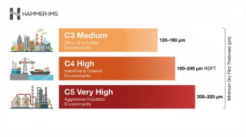
Industrial protective coatings: ISO 12944-5 outlines minimum dry film thickness requirements based on corrosivity environment:
| Corrosivity Class | Environment | Minimum NDFT (High Durability) |
|---|---|---|
| C3 (Medium) | Urban/Industrial | 120–160 µm |
| C4 (High) | Industrial/Coastal | 160–240 µm |
| C5 (Very High) | Aggressive Industrial | 200–320 µm |
These ranges provide the benchmark — deviations in either direction signal a problem worth investigating.
Minor Issues / Thin Readings
Readings towards the lower end of specification (e.g., below 75 microns / 3 mils for automotive clearcoat) indicate that aggressive correction or re-coating should not proceed. In industrial applications, low readings may signal under-application.
Actionable steps:
- Investigate spray gun settings and pressure
- Increase wet film thickness parameters upstream
- Perform a test area before proceeding with full production
- Document the deviation and consult coating specification datasheets
Out-of-Spec / Anomalous Readings
Readings significantly higher than surrounding panels (e.g., 40+ microns above the vehicle average) typically indicate rework, overspray, or body filler. In industrial contexts this can point to coating buildup, process drift, or equipment malfunction.
A "No Metal" or "Overflow" error reading often signals body filler, composite substrate, or a calibration issue and warrants immediate investigation before proceeding.
Uniformity is the primary indicator of quality. Large variations between adjacent panels, or across a single panel surface, are more telling than any single absolute number — in automotive detailing and industrial coating alike.
Common Errors and Best Practices When Measuring Paint Thickness
Even experienced operators can introduce measurement error through small, repeatable mistakes. The issues below are the most common sources of unreliable data—organised by error type so they're easier to audit against your own process.
Calibration failures:
- Skipping calibration entirely
- Zeroing on the wrong reference plate (such as using a steel shim on an aluminium substrate)
- Using worn or damaged calibration shims
- Failing to re-calibrate after battery changes or temperature shifts
Surface preparation failures:
- Measuring without cleaning the surface first
- Allowing dust, moisture, or oil to sit between probe and coating
- Measuring over wet or uncured coatings
Probe technique errors:
- Holding the probe at an angle rather than flat against the surface
- Dragging the probe laterally instead of lifting cleanly between readings
- Applying inconsistent pressure during measurements
Sampling errors:
- Taking only one or two spot measurements and treating them as representative of the entire surface
- Failing to measure over edges, body lines, or door jambs where thickness naturally varies
Context-specific pitfalls:
- On automotive panels, edges and body lines naturally read thinner than flat panels—don't interpret these as defects
- In industrial production settings, substrate temperature variation or surface texture (such as blast profile roughness) can introduce systematic error across an entire production run if not accounted for during calibration
Correcting these errors comes down to consistent process discipline. Apply these practices across every measurement workflow:
- Establish a documented measurement sequence defining where on each panel or production zone readings are taken
- Take a minimum of three measurements per zone and average them
- Re-calibrate whenever environmental conditions change significantly (temperature swings, humidity shifts)
- Log all results—by hand, software export, or connected data systems—to build a traceable record for quality assurance

For high-volume industrial production lines, manual logging and spot-checks aren't always sufficient. Hammer-IMS's Connectivity 3.0 software consolidates measurement data from multiple sensor types into a single system, enabling real-time process adjustments and automated feedback to coating systems without interrupting production.
Conclusion
Accurate paint thickness measurement comes down to three factors:
- Choosing the right technology for the substrate and coating type
- Following a disciplined, repeatable procedure — including calibration and surface preparation
- Interpreting results in context, not in isolation from process variables
Whether the application is verifying automotive OEM coating specs, confirming industrial coating compliance, or feeding measurements into real-time process control, these principles hold. Calibration, surface preparation, and systematic data collection are not optional steps — they are what separate a reliable measurement from a misleading one.
Frequently Asked Questions
How thick is 5 mils of paint?
5 mils equals 127 microns (since 1 mil = 25.4 microns). This thickness falls slightly above the typical factory automotive paint range of 100–180 microns and is near the lower end for industrial protective coatings in moderate corrosivity environments (ISO 12944 C3).
What is the difference between mils and microns when measuring paint thickness?
A mil is one-thousandth of an inch (0.0254 mm) while a micron (micrometre) is one-millionth of a metre (0.001 mm). Microns are generally preferred in precision industrial and automotive paint measurement because the smaller unit offers finer resolution for quality control.
Which paint thickness measurement method is most accurate?
Accuracy depends on the substrate: magnetic induction and eddy current gauges (±1–3%) are best for metals, while ultrasonic is required for plastics. For inline industrial applications, non-contact systems like M-Ray can match or exceed handheld accuracy while providing continuous real-time data at every point across the production surface.
How often should a paint thickness gauge be calibrated?
Gauges should be zeroed and checked against calibration shims at the start of every measurement session. Re-calibrate whenever batteries are replaced, substrates change, or there is a significant shift in ambient temperature. SSPC-PA 2 recommends verifying accuracy at the beginning and end of each work shift.
Can paint thickness be measured on plastic or non-metal surfaces?
Magnetic and eddy current gauges cannot read plastic or composite substrates. Ultrasonic gauges (with coupling gel) are required for accurate measurement on bumpers, fibreglass panels, and similar non-metal surfaces. Non-contact systems like Hammer-IMS's M-Ray technology also work effectively on plastics and composites in inline production environments.
What causes inconsistent paint thickness readings across the same panel?
The most common causes include:
- Natural process variation (overspray, gravity-driven flow during curing, surface geometry)
- Incorrect probe angle or placement
- Surface contamination
- Inadequate calibration
A difference of more than 35 microns within the same panel warrants closer investigation of application technique, equipment settings, or substrate preparation.