Introduction
Get membrane thickness wrong in either direction and the consequences are real. Too thin, and the membrane fails to deliver expected waterproofing, tensile strength, or barrier properties — risking warranty claims, field failures, and safety violations. Too thick, and manufacturers waste costly raw material without adding functional value.
The margin for error is narrow. In plastic film extrusion, for instance, reducing average film thickness from 0.8 mil to 0.7 mil delivers 15% material savings — which is only possible with accurate, consistent measurement.
Getting that accuracy right requires the right methods, tools, and workflows. This guide covers measurement techniques for membranes in both wet and cured states, how to choose between offline lab and inline production instruments, how to interpret readings against specification tolerances, and the pitfalls that most commonly compromise results.
Key Takeaways
- Membrane thickness is measured in microns or mils (0.001 inch); the right method depends on whether the membrane is wet or cured, and whether you're measuring offline or inline
- Mechanical contact gauges (micrometers) work best for cured sheet membranes in lab settings; wet mil gauges are standard for fluid-applied products
- Non-contact inline sensors deliver the most accurate, continuous thickness monitoring during manufacturing
- Always take multiple readings across the material surface—single-point measurements miss thickness variation and lead to non-conforming product approvals
- Misreading gauge notches and measuring on uneven surfaces are the most common sources of error
What Is Membrane Thickness and Why Accurate Measurement Matters
Membrane thickness is the physical distance between the two outer surfaces of a membrane layer, typically expressed in mils (thousandths of an inch) or microns (µm). One mil equals 0.001 inch, or approximately 25.4 microns—a conversion that matters whenever specs cross borders.
Thickness uniformity directly impacts performance and service life across industries:
- Waterproofing and roofing membranes fail prematurely when thickness falls below spec — water resistance and service life both drop
- Plastic films and packaging lose tensile strength, puncture resistance, and barrier integrity when thickness varies even slightly
- Nonwovens and automotive textiles require consistent thickness for acoustic insulation ratings and structural load performance
- Medical device films must meet dimensional tolerances defined by regulatory standards — deviation isn't a quality issue, it's a compliance failure

The financial stakes are concrete. In hose and tube extrusion, tighter thickness control delivered 5% material savings — €270,000 per year on a single line producing 600 kg/h. On the other side of the ledger, below-specification thickness in waterproofing membranes leads to coating failure and voided warranties.
What You Need to Measure Membrane Thickness
Tool selection comes down to three variables: membrane state (wet or cured), measurement context (lab or active production line), and required accuracy level.
Tools by Measurement Scenario
Wet fluid-applied membranes:
- Notched mil gauge (comb gauge)
Dry/cured sheet membranes:
- Micrometer or digital thickness gauge with flat anvils
Inline continuous production:
- Non-contact sensors (ultrasonic, laser, or millimeter-wave technology)
QC labs:
- Calibrated contact gauges traceable to national standards (NIST or equivalent)
Once you've matched tool to scenario, preparation determines whether readings hold up under scrutiny.
Preconditions and Setup
Substrate and surface:
- Ensure the surface is flat, clean, and free of debris or raised edges that could skew readings
- For wet measurements, work within the product's open time window
Calibration:
- Verify gauge calibration before each session using reference standards of known thickness
- Document calibration status and retain records for quality documentation
Environment:
- Avoid high-vibration areas when using contact methods
- For inline systems, confirm sensor standoff distance matches the material thickness range being processed
Methods to Measure Membrane Thickness Accurately
No single method suits all membrane types or production environments. The right method depends on membrane state (wet vs. cured), production stage (inline vs. offline), and required measurement precision.
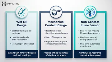
| Method | Best For | Measurement Stage |
|---|---|---|
| Wet Mil Gauge | Fluid-applied coatings and waterproofing | Immediately after application (wet) |
| Mechanical Contact Gauge | Cured, dry, or sheet-form membranes | Offline, post-cure |
| Non-Contact Inline Sensor | Fast-moving films, nonwovens, sheet materials | Continuous, during production |
Wet Mil Gauge (Notch/Comb Gauge)
Measures the wet thickness of fluid-applied membranes (spray, roll, or trowel-applied coatings and waterproofing) immediately after application, before curing.
Tools Needed: Notched mil gauge with graduated teeth at increasing heights
Step-by-Step:
- Apply the membrane product to the substrate as directed by the manufacturer; work within the specified open time
- Insert the gauge perpendicularly into the wet membrane immediately after application
- Remove the gauge and identify the highest numbered tooth with material on it and the lowest numbered tooth without material—the wet mil thickness falls between these two values
- Repeat in at least three to five separate locations to establish an average
Pros and Cons:
- Fast, low-cost, and requires no calibration equipment
- Gives a range rather than a precise single value
- Only works on wet material—readings cannot be taken after curing
- Destructive to the local surface
Mechanical Contact Gauge (Micrometer or Digital Thickness Gauge)
Measures the physical thickness of cured, dry, or sheet-form membranes by applying light mechanical contact pressure between two flat anvils.
Tools Needed: Calibrated micrometer or digital contact thickness gauge with flat anvils appropriate for the material stiffness and thickness range
Step-by-Step:
- Zero the gauge against its calibration standard or a reference shim of known thickness; confirm the gauge reads within acceptable tolerance
- Place the membrane sample flat on a stable surface; lower the gauge anvil gently onto the sample, avoiding excess pressure that could compress soft or foam-type membranes
- Record the reading, then repeat at a minimum of five evenly distributed points across the sample width and length
- Calculate the mean and note the maximum deviation from spec
Pros and Cons:
- High accuracy and repeatability for rigid or semi-rigid cured membranes
- Simple to operate with calibrated equipment
- Offline method unsuited for continuous production monitoring
- Soft or compressible materials require controlled anvil pressure to avoid compression errors—ASTM D5199 specifies 20 kPa contact force, but this can artificially compress nonwovens and foams
Non-Contact Inline Measurement (Ultrasonic, Laser, or Millimeter-Wave Sensors)
Measures membrane thickness continuously during production without physical contact, making it suitable for fast-moving films, nonwovens, and sheet materials where stopping to measure is impractical.
Tools Needed: Non-contact sensor system (ultrasonic, laser displacement, or millimeter-wave technology) mounted above and/or below the production line, integrated with a data acquisition system
Step-by-Step:
- Mount the sensor system at the designated measurement point on the production line; configure the standoff distance and calibrate the sensor against samples of known thickness before production begins
- Run the production process; the sensor continuously emits and receives signals, calculating thickness at high frequency across the material width
- Monitor the real-time data output on the control interface; use the feedback to adjust process parameters (such as die gap, line speed, coating weight) to maintain thickness within tolerance without stopping production
Pros and Cons:
- Enables 100% coverage measurement rather than spot-checks
- Supports closed-loop production control
- Eliminates sampling downtime and contact-based compression errors
- Terahertz Time-of-Flight (THz-TOF) systems measure reference samples with ±1.5 µm accuracy at 700 mm/s line speeds, outperforming manual micrometers (±2.5 µm)
- Higher upfront investment compared to manual gauges
Hammer-IMS M-Ray systems apply non-nuclear millimeter-wave technology to deliver contactless, real-time thickness data for plastic films, nonwovens, and coated materials. Because millimeter-wave signals are independent of product temperature, M-Ray sensors can be installed immediately post-die for hot-melt thickness control — a position where ultrasonic sensors cannot reliably operate.
How to Interpret Membrane Thickness Results
A raw thickness number is only meaningful when evaluated against the relevant specification. Misinterpreting results (or taking too few readings) risks approving non-conforming product or triggering unnecessary rework.
On-Spec / Acceptable Range
The measurement falls within the manufacturer's specified thickness range or project specification (e.g., minimum dry film thickness or nominal gauge). Confirm that readings from all sample locations fall within this band, not just the average. Record and retain measurement data as part of quality documentation.
Minor Deviation (Near-Tolerance)
When one or more readings fall slightly outside spec but within an acceptable variation band, the first step is to determine the cause:
- Localized deviation (edge or seam inconsistency): apply additional material to thin areas while still within open time
- Systematic deviation (process setting drift): adjust machine settings before the next production run
Out-of-Spec / Reject Condition
Readings are consistently below minimum or above maximum specification:
- Below-spec membranes must be rejected or recoated before curing—installing an under-thickness waterproofing membrane risks warranty voidance and field failure
- Above-spec adds direct material cost and may cause adhesion or compatibility problems
- For inline production, out-of-spec trending is a signal to halt the line, inspect the sensor and process settings, and requalify before continuing
- Inline systems like Hammer-IMS Connectivity 3.0 software can trigger automatic alerts and closed-loop adjustments to prevent out-of-spec product from reaching downstream processes
Sampling Strategy
A single point measurement is insufficient. For lab measurements, the minimum recommended sampling is at least 5 points per sample area. Inline systems go further: full-width scanning provides continuous thickness mapping across the entire material web, making it significantly more reliable than intermittent spot-checks for detecting gradients and localized thin spots.
Common Errors When Measuring Membrane Thickness
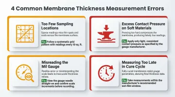
Most membrane thickness errors don't come from faulty instruments — they come from how and when measurements are taken. These four mistakes account for the majority of inaccurate or non-representative results:
Too few sampling locations: Measuring only one or two points and treating them as representative is the leading cause of missed non-conformance. Thickness variation across a membrane web can be significant, so sampling protocols must define the minimum number and distribution of measurement points.
Excess contact pressure on soft materials: Applying too much anvil pressure on foam membranes, nonwovens, or compressible coatings produces readings below actual thickness. Use gauges with defined contact force, or switch to non-contact methods — Electromagnetic Acoustic Resonance (EMAR) achieves <0.2% relative accuracy without touching the material.
Misreading the mil gauge: Misidentifying the last wet tooth versus the first dry tooth is common, especially with thin coatings. Check in good lighting and re-insert the gauge in a fresh spot rather than re-reading the same puncture.
Measuring too late in the cure cycle: Taking wet readings after the membrane has begun to skin over produces falsely low results — the gauge can no longer penetrate the partially cured surface. Measurement must happen within the product's open time window.
Best Practices and Safety Tips
Best Practices and Safety Tips
Calibrate before every measurement session. All gauge types — from manual mil gauges to inline sensors — drift over time or after impacts. Document calibration dates, reference standards used (such as NIST-traceable standards specified in ASTM D8136 for non-contact capacitance gauges), and any out-of-tolerance findings to maintain a defensible quality record.
Establish a written measurement protocol to eliminate operator-to-operator variability. At minimum, define:
- Number and location of measurement points
- Sampling pattern (such as grid or cross-web)
- Measurement frequency for inline systems
- Acceptable tolerance bands
- Corrective action procedure when readings fall out of spec
Safety and handling precautions:
- When working with wet fluid-applied membranes, wear appropriate PPE (gloves, eye protection, respiratory protection if required) and ensure adequate ventilation as specified in the product SDS
- Keep measurement areas free of contamination—dust, adhesive residue, or surface moisture on the substrate can alter both the application and the reading
- For inline sensor systems, follow the equipment manufacturer's lockout/tagout procedures before performing maintenance or repositioning sensors near moving machinery
Conclusion
Accurate membrane thickness control starts with choosing the right measurement method for your process:
- Wet mil gauge for fluid-applied coatings during application
- Contact micrometer for cured sheets and discrete samples
- Non-contact inline measurement for continuous production lines
Thickness data collected at sufficient sampling points — and compared against specification tolerances — enables immediate corrective action. That prevents costly field failures, warranty claims, and material waste before they occur.
The payoff can be substantial. Case studies show manufacturers reducing thickness safety margins by 90% — from 200 micrometres to 20 micrometres — saving over 1,000 metric tonnes of raw material annually through inline measurement systems.
Frequently Asked Questions
How to measure membrane thickness?
The method depends on membrane state: use a notched wet mil gauge for fluid-applied membranes while wet, a contact micrometer or digital gauge for cured/dry sheet membranes, and a non-contact inline sensor for continuous production monitoring. Always take multiple readings across the surface to confirm uniformity.
What is membrane thickness?
Membrane thickness is the physical distance between a membrane's two outer surfaces, typically measured in mils (thousandths of an inch) or microns (µm). Specified thickness values ensure the membrane delivers its intended performance for waterproofing, gas barrier, acoustic insulation, or structural protection applications.
What does 1 mil thickness mean?
1 mil equals 0.001 inch or approximately 25.4 microns. Mils are commonly used in the waterproofing, coatings, and film industries to specify product application thickness. A typical fluid-applied waterproofing membrane requires 60–100 wet mils to achieve the target cured dry film thickness.
What is the most accurate method for measuring membrane thickness in production?
Inline non-contact measurement systems (ultrasonic, laser, or millimeter-wave) offer the highest accuracy and coverage during live production because they scan continuously across the full material width without stopping the line or introducing contact-based distortions.
Can membrane thickness be measured without contact?
Yes. Non-contact methods—including ultrasonic pulse-echo, laser displacement, and millimeter-wave (M-Ray) technology—measure thickness without touching the material. Laser ultrasonic methods measure individual layer thicknesses in laminates with relative errors between just 1.48% and 2.17%, making them well-suited for delicate films, high-speed lines, or any material where contact pressure would distort the reading.
What tools are used to measure membrane thickness?
Notched mil gauges for wet fluid-applied products; calibrated digital micrometers or contact thickness gauges for cured or sheet-form membranes in lab or QC settings; and automated inline sensor systems (ultrasonic, laser, or millimeter-wave) for real-time production monitoring.