Introduction
OSB panel thickness is a critical quality parameter that directly affects structural performance, span ratings, and compliance with standards like PS 2, EN 300, and APA Rated Sheathing classifications. What many production teams and inspectors fail to recognize is that nominal thickness—the category stamped on the panel, such as "15/32"—is not the same as actual measured thickness, which might read 0.451 in. on a micrometer. That gap matters.
In North America, PS 2 tolerances allow only ±0.8 mm for panels ≤13/16", while in Europe, EN 300 sets ±0.3 mm for sanded panels. A panel measuring just 0.2 mm out of tolerance may fail compliance testing, triggering rejected shipments and rework costs.
Up to 70% of quality deviations occur before final inspection — which means delayed detection directly translates to wasted material.
This guide covers the tools, step-by-step methods, and interpretation criteria for accurately measuring OSB panel thickness, whether on the production floor, in a QC lab, or at a job site.
Key Takeaways
- OSB panels have a nominal thickness (e.g., 7/16" / 11 mm) and an actual measured thickness: always verify against the applicable standard tolerance
- Three measurement methods apply: manual calipers, digital micrometers/ultrasonic gauges, and non-contact inline systems
- Measurement location matters—always measure at least 50 mm in from edges where moisture-induced swelling is most common
- Out-of-tolerance panels risk span rating non-compliance, load capacity failure, and rejected shipments
- Inline non-contact systems eliminate human error and enable real-time closed-loop production adjustments
What You Need to Measure OSB Panel Thickness
Choosing the right measurement method depends on whether the goal is spot-checking individual panels in the field or lab, or continuous monitoring across an entire production run. The key distinction lies between contact methods—where a physical instrument touches the panel—and non-contact approaches that measure without touching the panel surface.
Tools and Indicators Required
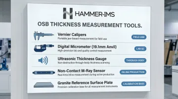
Core measurement tools include:
- Vernier calipers (0–50 mm range, 0.02 mm resolution minimum) for field inspections
- Digital micrometers with 19.1 mm diameter anvils for lab-grade spot checks—PS 2 mandates this anvil size at 34–69 kPa pressure to prevent compressing OSB's textured surface strands
- Ultrasonic thickness gauges for panel body measurement without edge access, using 1–5 MHz transducers and glycerin coupling gel
- Non-contact millimetre-wave or M-Ray sensors (such as those from Hammer-IMS) for inline production use
- Flat reference surface (granite surface plate or equivalent) needed for all contact methods to ensure panel stability
Preconditions and Setup
Panels must be conditioned to stable moisture content before measurement. OSB exhibits edge flare that can be 0.5–3.8 mm thicker at panel edges than at 100 mm from the edge after moisture exposure. Surface moisture from rain or construction delays will cause artificially high edge readings.
Critical setup steps:
- Measure at least 50 mm in from the panel edge (PS 2 specifies 19–25 mm from edge for thickness readings)
- Place panels flat on a level surface with no bowing or stacking distortion
- Ensure the measurement surface is clean and free of sawdust or resin deposits
- Check for panel curvature before each reading, as any bowing will skew caliper results
Methods to Measure OSB Panel Thickness
Multiple methods exist for OSB thickness measurement, ranging from manual spot-check tools to automated inline systems. The right method depends on three factors: required accuracy, production volume, and whether measurement needs to be destructive or non-destructive.
Method 1: Manual Caliper Measurement
Manual calipers use direct physical contact to measure panel thickness at discrete points. This method suits field inspections, incoming goods checks, and low-volume QC sampling.
Tools Needed:
- Digital or vernier calipers with sufficient jaw depth to reach panel centre
- Flat reference surface
- Measurement location markings
Step-by-Step:
Mark measurement points - Place the OSB panel flat on a stable, level surface. Mark five measurement points: panel centre, and four points at least 50 mm from each edge midpoint (avoiding tongue-and-groove profiles if present)
Position calipers properly - Open the caliper jaws wider than the estimated panel thickness and position them perpendicular to the panel face. Close the jaws gently until they make flush contact with both faces—do not over-tighten, as excessive jaw pressure compresses the surface strand layer of OSB, producing readings 0.2–0.5 mm lower than actual thickness
Record and calculate - Record the reading at each of the five points. Calculate the average and compare against the applicable tolerance (e.g., PS 2 tolerance: +0.0/-1/32 in. for most categories; EN 300 tolerance: ±0.3 mm for panels ≤18 mm)
Advantages:
- Low cost and portable
- Appropriate for job site verification and receiving inspection
- No calibration complexity
Limitations:
- Limited to spot checks only
- Operator-dependent accuracy
- Susceptible to error on rough or textured OSB surfaces
- Cannot detect within-panel thickness variation across the full sheet
Method 2: Digital Micrometer and Ultrasonic Gauge Measurement
This method covers two higher-precision options: digital micrometers (contact-based) and ultrasonic gauges (through-body). Both suit laboratory QC, panel grading, and manufacturer compliance testing — and ultrasonic gauges have the added advantage of measuring thickness without requiring access to both faces simultaneously.
Tools Needed:
- Calibrated digital micrometer (resolution ≥0.001 mm) for bench QC
- Ultrasonic pulse-echo thickness gauge with 1–5 MHz transducer frequency suitable for wood-based panels
- Coupling gel (glycerin or high-viscosity gel) required for ultrasonic measurement
Step-by-Step:
For digital micrometer:
- Secure the panel on a flat surface. Position the micrometer anvil and spindle perpendicular to the panel face
- Apply consistent spindle pressure per instrument calibration protocol—PS 2 specifies 34–69 kPa (5–10 psi)
- Take readings at the five standard points; log results for statistical analysis
For ultrasonic gauge:
- Apply a thin layer of coupling gel to the panel face at the measurement point—glycerin works well for wood composites due to high viscosity and acoustic impedance
- Press the transducer flat against the surface, perpendicular to the panel face
- Allow the reading to stabilise (typically 1–2 seconds) and record the value
- Clean the coupling gel before moving to the next point
- Compare individual readings and standard deviation across all measurement points to the applicable standard tolerance
Advantages:
- Far higher precision than calipers
- Suitable for compliance-grade QC testing
- Ultrasonic gauges eliminate the need to access both faces
- Enables measurement of stacked or installed panels
Limitations:
- Equipment calibration required
- Coupling gel introduces a consumable cost
- Signal attenuation in OSB's multi-layered, porous structure requires lower-frequency transducers
- Neither method can scan the full panel continuously during production
Method 3: Non-Contact Inline Thickness Measurement
Fully automated and non-contact, this approach uses millimetre-wave (M-Ray) or similar sensor technology to continuously measure OSB panel thickness across the full production line width at production speed. It's built for real-time quality control and closed-loop process adjustment in high-volume manufacturing.
Tools Needed:
- Non-contact inline thickness measurement system (such as Hammer-IMS M-Ray sensor arrays)
- Mounting frame spanning the production conveyor
- Data acquisition and process control interface
Step-by-Step:
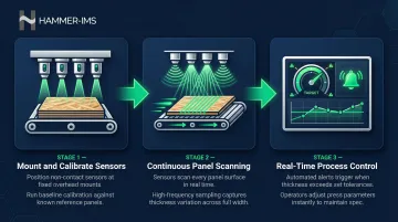
Mount and calibrate sensors - Mount the sensor array above (and, if applicable, below) the production conveyor at the designated measurement station—typically after the press and before the panel trimming stage. Calibrate the system against reference panels of known thickness per manufacturer protocol
Continuous scanning during production - During production, the sensor continuously scans each panel as it passes beneath, measuring thickness at multiple points across the full panel width simultaneously. The system logs a complete thickness profile (not just spot values) for every panel produced
Real-time process control - Feed measurement data in real time to the process control system. Configure alert thresholds based on the applicable tolerance (e.g., ±0.3 mm from target for EN 300 compliance). Out-of-tolerance readings trigger automatic alerts or closed-loop press adjustments without stopping the line
Advantages:
- Eliminates sampling error—every panel is measured, not just a statistical sample
- Provides full cross-width thickness profiles, enabling detection of edge-to-centre taper or press non-uniformity
- Non-contact and non-nuclear, meaning no radiation safety requirements and no surface damage
- Reduces typical 25% material overdosing seen without inline measurement
Limitations:
- Initial installation cost is higher than manual methods
- Requires integration with existing production control systems
- Payback timeline varies — sustained production volume is required to offset installation investment
How to Interpret OSB Thickness Measurement Results
What a reading means depends entirely on the applicable standard and the panel's intended application. A 7/16" (11 mm) category panel that measures 0.395 in. instead of 0.418 in. may be out of PS 2 tolerance—and that deviation can affect span rating compliance and load capacity. The subsections below map each outcome type to a clear next action.
Normal/Acceptable Results
A compliant result means the measured thickness falls within the published tolerance band for the performance category.
PS 2 (North America) Thickness Tolerance Table:
| Performance Category | Minimum Thickness (mm) | Minimum Thickness (in.) | Maximum Thickness (mm) | Maximum Thickness (in.) |
|---|---|---|---|---|
| 3/8 | 8.73 | 0.344 | 10.32 | 0.406 |
| 7/16 | 10.32 | 0.406 | 11.91 | 0.469 |
| 15/32 | 11.11 | 0.438 | 12.70 | 0.500 |
| 19/32 | 14.29 | 0.563 | 15.88 | 0.625 |
| 23/32 | 17.46 | 0.688 | 19.05 | 0.750 |
| 1-1/8 | 27.15 | 1.069 | 30.00 | 1.181 |
EN 300 (Europe):
- Sanded OSB: ±0.3 mm tolerance
- Unsanded OSB: ±0.8 mm tolerance
Actionable step: Panels within tolerance pass QC and proceed.
Minor Issues — Edge Swell
OSB panels commonly show edge swell after moisture exposure, where the measured edge thickness can be significantly higher than the panel body. Up to 73% of total thickness swell can occur in the highly densified top and bottom face regions during early moisture exposure.
This is a cosmetic condition and does not necessarily indicate a structural non-conformance per PS 2, provided the panel body readings are within tolerance.
Actionable step: Sand raised edges flat, re-measure at least 50 mm from the edge, and re-evaluate against the standard before rejection.
Out-of-Spec Results
Readings that fall outside the published tolerance in the panel body (not just at edges) indicate a potential non-conformance.
Possible causes:
- Press pressure variability
- Resin content inconsistency
- Mat formation issues
Actionable steps:
- Quarantine affected panels
- Trace back to production batch and press settings
- Investigate root cause
- Assess whether panels can be re-graded to a lower performance category or must be scrapped
On production lines, a thickness profile showing a consistent taper across panel width points to a press alignment issue rather than a material defect. Real-time thickness profile data from inline non-contact systems makes this distinction immediately visible. That speed of diagnosis enables press correction before additional panels are affected—something periodic manual sampling cannot reliably deliver.
Common Errors in OSB Thickness Measurement
Four errors account for the majority of out-of-tolerance OSB readings. Each is avoidable with straightforward technique and preparation.
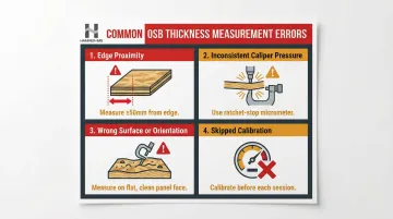
Edge proximity: OSB edges can be 0.5–3.8 mm thicker than the panel body measured 100 mm inward. Readings taken within 25–30 mm of any edge will read artificially high. Measure at least 50 mm from the edge.
Inconsistent caliper pressure: Excessive jaw pressure compresses OSB's surface strand layer, producing readings 0.2–0.5 mm below actual thickness. Use a ratchet-stop micrometer or establish a fixed closing-force protocol to remove operator variability.
Wrong surface or orientation: An uneven support surface, a skid-resistant coating, or a T&G profile will all introduce error. Take readings on the flat, clean face of the panel body — not across textured or profiled areas.
Skipping instrument calibration: Digital calipers need zero-calibration; ultrasonic gauges also require velocity calibration specific to wood-based panel material. Omitting either step introduces a systematic offset that skews every reading in the session.
Best Practices for Reliable OSB Thickness Measurement
Implement a defined measurement plan for incoming and outgoing QC: specify the number of panels sampled per lot, measurement point locations per panel, and acceptable AQL (Acceptable Quality Level) thresholds aligned to PS 2 or EN 300 requirements. Document all results with panel batch codes, production date/time, and operator ID for traceability.
Where production tolerances are tight or throughput is high, transition from periodic sampling to continuous inline measurement. 100% inline inspection provides real-time data that prevents the typical 25% material overdosing seen without inline measurement. The financial case is clear: the Cost of Poor Quality (COPQ — including scrap, rework, downgrading, and warranty claims) can reach 15–20% of total sales revenue in manufacturing, and in wood products specifically, total CoQ reaches 11% of sales and 15% of material cost.
Non-contact inline systems measuring every panel at full production speed catch systematic press drift early, reduce waste from out-of-tolerance runs, and supply the data needed for closed-loop process control — none of which periodic 5–10% sampling can reliably deliver.
Maintain instrument calibration records and schedule periodic re-calibration against certified reference standards. Specific checks by instrument type:
- Contact instruments: Inspect for jaw wear and anvil flatness regularly
- Ultrasonic gauges: Verify velocity calibration on a known-thickness reference panel each measurement session
Conclusion
Accurate OSB thickness measurement ensures panels actually meet the performance categories and span ratings they are stamped with. Whether you are using a manual caliper for field verification, a precision lab instrument for compliance testing, or a continuous non-contact inline system for production, measurement is what separates a verified specification from a printed label. A stated "7/16 category" panel that has not been measured is an assumption, not a confirmed result.
The method chosen should match the use case:
- Incoming goods and job site checks — manual calipers for quick, portable spot verification
- QC lab compliance testing — higher-precision instruments where documented accuracy is required
- Production environments — automated inline systems that verify every panel and enable real-time process corrections
Match the tool to the task, and panel rejections, rework costs, and code compliance concerns largely take care of themselves.
Frequently Asked Questions
What is a non-contact thickness measurement?
Non-contact thickness measurement uses sensor technologies such as millimetre-wave or laser-based systems to measure material thickness without touching the surface, enabling continuous inline measurement at production speeds without risk of surface damage or operator error.
What is the thickness profile measurement?
A thickness profile measurement captures thickness values at multiple points across the width (and sometimes length) of a panel, rather than a single spot reading. This reveals variations such as edge-to-centre taper, press non-uniformity, or localised defects that a single-point reading would miss.
What is a non-contact width measurement?
Non-contact width measurement uses optical or sensor-based systems to measure a panel's physical width without contact. It is often performed simultaneously with thickness measurement in inline production systems to confirm dimensional compliance across both axes.
What is the standard thickness tolerance for OSB panels?
Tolerances vary by standard: PS 2 (North America) allows ±0.8 mm (1/32 in.) for panels ≤13/16" category, and ±5% for thicker panels. EN 300 (Europe) sets ±0.3 mm for sanded OSB and ±0.8 mm for unsanded OSB.
What is the difference between nominal and actual OSB thickness?
Nominal thickness refers to the performance category label (e.g., "7/16 category"), whilst actual thickness is the measured dimension (e.g., 0.418 in.). The APA trademark stamp on compliant panels includes both values, and actual thickness is what must be verified against tolerance standards.
How often should OSB thickness be checked during production?
Sampling frequency depends on production volume and quality system requirements. Inline non-contact systems enable 100% panel coverage continuously, whereas manual sampling protocols typically specify a minimum number of measurements per shift or per production lot under the applicable QC standard.