Introduction
GPS (Graphite Polystyrene) insulation adoption is accelerating across the construction sector, with the global market projected to reach USD 4.47 billion by 2031, driven by a 7.5% compound annual growth rate. This rapid expansion puts direct pressure on manufacturers to deliver boards that meet tight thermal and mechanical specifications across every production run.
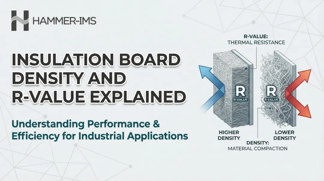
Quality in GPS boards extends far beyond visual inspection. Density variations, thickness inconsistencies, and non-uniform graphite distribution are invisible to the naked eye, yet each one directly undermines R-value performance and compressive strength — the two parameters that determine ASTM C578 classification.
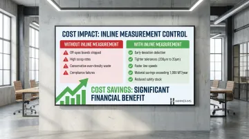
Without reliable inline measurement, production lines risk shipping off-spec boards, accumulating costly scrap, or triggering compliance failures that erode both margins and customer trust.
What follows covers how modern, non-nuclear inline measurement technologies make it possible to control GPS board quality in real time — closing the loop on process adjustments and eliminating the material waste that results from producing to conservative safety margins instead of exact specifications.
Key Takeaways
- GPS board quality hinges on three parameters: density, thickness uniformity, and graphite distribution
- Board density directly determines ASTM C578 classification, R-value, compressive resistance, and moisture performance
- Inline measurement of areal weight and thickness profile delivers real-time density calculations across the full board width
- Non-nuclear, contactless systems provide continuous data without disrupting production or requiring radioactive source permits
- Closed-loop control reduces material overuse and scrap rates while maintaining consistent on-spec output across every board
What Is GPS Insulation Board Quality Measurement?
GPS insulation board quality measurement is the systematic, inline or offline process of measuring physical parameters—primarily density, thickness, and uniformity—of Graphite Polystyrene foam boards during or immediately after production to verify conformance with product specifications and industry standards.
GPS foam behaves differently from standard EPS in ways that matter directly to measurement. The graphite particle infusion alters three key properties:
- Material density — graphite addition increases mass per unit volume, affecting structural classification
- Infrared absorption — graphite particles block over 90% of radiative heat transfer, a primary driver of thermal performance
- Thermal conductivity — uniform graphite dispersion is what separates a well-made GPS board from an underperforming one
Density control, then, is a thermal performance variable—not just a structural one. Inconsistent graphite distribution means inconsistent R-value, regardless of what the label states.
ASTM C578 Classification Requirements
ASTM C578 serves as the governing standard for GPS rigid insulation classifications in North America. The standard defines Types I through XV based on minimum density thresholds and corresponding performance requirements:
| ASTM Type | Min. Density (lb/ft³) | Min. Compressive Resistance (psi) | Min. R-Value per inch @ 75°F |
|---|---|---|---|
| Type I | 0.90 | 10.0 | 3.6 |
| Type VIII | 1.15 | 13.0 | 3.8 |
| Type II | 1.35 | 15.0 | 4.0 |
| Type IX | 1.80 | 25.0 | 4.2 |
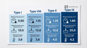
GPS products typically deliver R-values of 4.7 to 5.0 per inch—significantly higher than standard EPS at equivalent densities. Production measurement systems must verify that every board meets these classification targets.
Why Density and Quality Control Matter in GPS Board Production
Density: The Master Variable
GPS board density simultaneously controls R-value per inch, compressive strength, water vapor permeance, and flexural strength — and each ASTM C578 density tier maps to a different performance classification and application suitability. Get density wrong in either direction, and the consequences ripple through compliance, cost, and customer relationships.
Under-Density Failure Mode
Boards produced below target density deliver lower-than-specified R-value, fail compressive resistance tests, and may be misclassified into the wrong ASTM type. This results in:
- Rejected shipments and warranty liability
- Damaged customer relationships
- Failed code compliance inspections
- Lost revenue from scrapped material
ISO 4898 sets a hard floor: no single specimen shall be less than 90% of the minimum density requirement. This "90% rule" means even one out-of-spec board in a batch can trigger rejection of the entire production run.
Over-Density Failure Mode
Under-density creates compliance risk — but over-density quietly erodes profitability. Producing boards denser than required wastes raw material without delivering additional customer value. With EPS resin prices around USD 1,200/MT and graphite at USD 876/MT, systematic over-density compounds into significant material waste. Over-density also:
- Increases product weight and shipping costs
- Reduces breathability (vapor permeance rating)
- Erodes profit margins through unnecessary material consumption
One case study found that processing GPS scrap reduced waste removal costs by nearly USD 10,000 per month for a single facility — a direct measure of what density control failures cost at scale.
Cross-Board Density Variation
Even boards that pass average density checks can fail in practice. Variation across a single board — in the Z-direction or cross-machine direction — creates zones of differential thermal resistance within one panel.
This matters most in continuous insulation applications where thermal bridging must be eliminated. Non-uniform graphite dispersion creates radiative heat leak pathways that degrade effective R-value even when the batch average meets specification.
Business Case for Inline Measurement
Consistent quality control through measurement delivers:
- Reduced scrap rates through early deviation detection
- Lower safety stock requirements
- Tighter production tolerances (200 micrometres to 20 micrometres)
- Faster line speeds with maintained quality
- Compliance with customer and certification specifications
- Material savings exceeding 1,000 metric tonnes annually on high-volume lines
Key Quality Parameters to Measure in GPS Insulation Boards
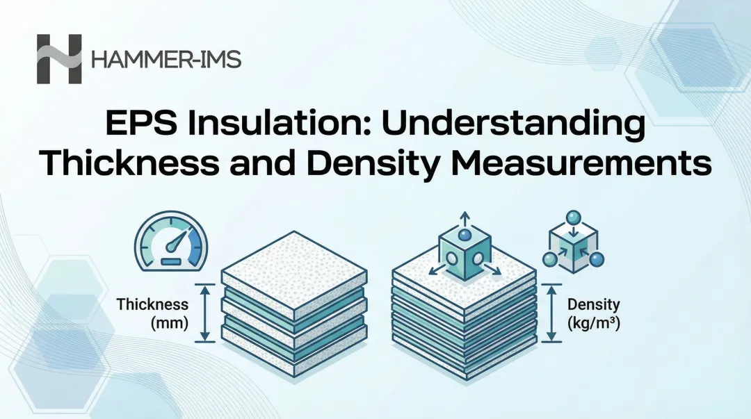
Density / Areal Weight
Direct density measurement in a running foam line is complex. The practical approach measures areal weight (mass per unit area) using transmission-based systems. From areal weight and known thickness, density can be derived in real time using the formula: Density = Areal Weight ÷ Thickness.
Areal weight measurement is the primary production KPI for GPS boards because it directly correlates to both material cost and thermal performance.
Thickness Profile
Thickness must be measured across the full width (cross-machine direction profile), not just at the board centerline. This detects:
- Taper from uneven die gaps
- Crowning from differential cooling
- Edge compression from handling
- Systematic thickness drift
Contact-based methods risk surface marking on soft GPS foam. Non-contact methods—laser triangulation, ultrasonic, or millimeter-wave—are preferred for maintaining surface integrity.
Machine Direction Thickness Uniformity
High-frequency sampling (multiple kHz range) resolves cyclic thickness patterns that average-based sampling misses entirely. These periodic variations typically trace back to:
- Roll pressure fluctuations in the calibration zone
- Cutting speed inconsistencies
- Bead expansion irregularities
- Specific mechanical components, such as individual extrusion screw bolts (identifiable through frequency analysis)
Surface and Facer Uniformity
For GPS boards with laminated film facers, the uniformity of facer adhesion and coverage affects vapor permeance classification and product appearance. This parameter matters commercially for premium product lines.
Graphite Distribution Uniformity
Non-uniform graphite dispersion creates localized hot spots of higher thermal conductivity. Measuring this directly inline is difficult, but density and IR-transmittance signals provide indirect indicators. Studies have shown that just 1 wt% expanded graphite can block over 90% of radiative thermal conductivity—but only when uniformly dispersed. Until dedicated inline graphite-uniformity sensing becomes standard, cross-referencing IR-transmittance data against density readings is the most practical approach for production QC.
How GPS Insulation Board Quality Measurement Works – Step by Step
This section walks through the practical stages of setting up and operating an inline quality measurement process for GPS foam board production. The most common failure is treating measurement as an end-of-line audit rather than a live production control tool.
Step 1 – Define Specification Targets
Establish the target density range, thickness tolerance, and width profile specification for the GPS board type being produced. For example:
- Type I GPS: 0.90 lb/ft³ minimum density, ±0.05 lb/ft³ tolerance
- Type II GPS: 1.35 lb/ft³ minimum density, ±0.05 lb/ft³ tolerance
- Thickness: ±2% of nominal thickness
- Width profile: Maximum 3% variation across cross-machine direction
These become the control limits for the measurement system. Specs should be defined per customer requirement AND per certification standard, as they may differ.
Step 2 – Select and Position the Measurement System
Choose between contact (mechanical caliper) and non-contact (ultrasonic, millimeter-wave, or laser) measurement. For GPS foam, non-contact systems are the practical choice because they:
- Avoid surface deformation on soft foam
- Measure across full board width in scanning or array configuration
- Enable higher sampling frequencies without mechanical wear
Position sensors before and after any cutting or pressing stage to isolate sources of variation. Measuring 9 metres upstream allows prompt adjustment of extrusion parameters before material waste accumulates.
Step 3 – Calibrate to GPS Material Properties
GPS foam's graphite content affects its interaction with measurement technologies. Dielectric properties differ from standard EPS, and graphite particles influence millimeter-wave propagation. Calibration must be performed using GPS-specific reference samples across the full density range (0.90 to 1.80 lb/ft³).
Poor calibration is the most common cause of systematic measurement offset in foam production environments. Systems should support automatic calibration routines that maintain long-term accuracy without manual intervention.
Step 4 – Run Continuous Inline Measurement
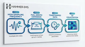
Continuous data acquisition across the board width and along the machine direction generates a 2D density and thickness map in real time. Key requirements:
- High sampling frequency: Multiple kHz measurement rates to detect short-wavelength variation
- Full-width coverage: Multi-sensor arrays or scanning frames covering up to 5+ metres
- Timestamped data: Linked to production parameters (line speed, steam pressure, expansion time) for root cause analysis
- 2D visualisation: Colourmap displays showing highs and lows across the entire board surface
This continuous data stream provides the statistical basis to demonstrate conformity — giving far greater confidence than any spot-check sampling regime can offer.
Step 5 – Interpret Results and Trigger Closed-Loop Adjustments
Measurement data feeds into process control:
- If density trends low: Signal adjustment to bead expansion parameters or steam pressure
- If thickness drifts: Correct cutting or pressing station parameters
- If cross-direction variation appears: Adjust die gap or cooling roll pressure
This closed-loop capability is what makes inline measurement genuinely superior to offline sampling. Real-time alerting on out-of-tolerance conditions prevents entire production runs from being scrapped. At one GPS board facility, this approach achieved payback within 1.5 years through material savings and waste reduction.
How Hammer-IMS Can Help
Hammer-IMS's M-Ray measurement technology is a non-nuclear, millimeter-wave-based contactless system designed for continuous inline density and thickness measurement of foam and insulation board products. M-Ray transmits millimeter-wave signals through the GPS board to derive areal weight and thickness simultaneously, without touching the product surface or requiring any radioactive source.
Key Production Benefits
- Real-time cross-profile scanning: Multi-sensor arrays provide near-100% material coverage
- High-speed compatibility: Measurement rates in the multiple kHz range support fast production lines
- Connectivity 3.0 software: Data logging, timestamped records, and integration with recipe/batch systems
- Closed-loop integration: Direct feedback to production control systems for automatic parameter adjustment
- Non-nuclear technology: Eliminates radioactive licensing, safety protocols, and disposal requirements
Hammer-IMS systems are already deployed with construction materials manufacturers and foam producers globally, including Abriso-Jiffy (XPS insulation boards) and Federal Eco Foam (recycled foam insulation). The non-nuclear approach also simplifies regulatory compliance, removing the licensing and safety overhead traditionally associated with nuclear gauges.
For GPS, EPS, and XPS panel insulation lines specifically, the Marveloc-CURTAIN solution offers two flexible configurations:
- CURTAIN C-Frame: Compact installations up to 1.5 metres wide
- CURTAIN O-Frame: Wide production lines of 5+ metres
Both systems measure before or after cross-linking and work with all colour masterbatches without recalibration.
Frequently Asked Questions
What is GPS insulation?
GPS (Graphite Polystyrene) is expanded polystyrene foam infused with high-purity graphite particles. These particles reflect and absorb infrared radiation, increasing thermal resistance and making GPS more energy-efficient than standard EPS at the same thickness.
What is the R-value per inch of GPS insulation?
GPS insulation typically delivers an R-value of approximately 5.0 per inch at 75°F, which is higher than standard EPS (~3.85 per inch) and comparable to XPS. This R-value remains stable over time because GPS uses air as a blowing agent rather than gases that degrade.
Is GPS foam better than XPS foam?
GPS matches XPS on R-value while offering more stable long-term thermal resistance, better moisture drying characteristics, and significantly lower global warming potential (1.19 kg CO₂ eq vs. 21.9 kg CO₂ eq per m² at RSI-1). For above-grade and below-grade applications where sustainability matters, GPS is the stronger long-term choice.
Why does density matter in GPS insulation board production?
GPS board density directly determines its ASTM C578 classification, compressive resistance, R-value, and vapor permeance. Under-density boards are thermally underperforming and off-spec; over-density boards waste raw material. Even a 5% density deviation can push a board outside its rated classification, making inline density control essential to both quality assurance and material efficiency.
How is GPS foam board density measured during production?
Inline density is inferred from areal weight measurement using transmission-based systems (such as millimeter-wave or microwave gauges), combined with thickness data. Non-nuclear systems are the practical standard: they require no licensed radiation operator, carry no permitting burden, and can be installed or relocated without regulatory approval.
Can GPS insulation board thickness be measured without contact?
Yes. Non-contact measurement using laser, ultrasonic, or millimeter-wave technology is the right approach for GPS foam boards. GPS foam's soft surface deforms under mechanical contact gauges, introducing measurement error. Non-contact systems enable full-width profile scanning without slowing the production line.