Introduction
Film gauge thickness is a critical quality and process control parameter in plastic film and sheet production. It's not simply a labeling convention — it's a specification that directly determines barrier performance, mechanical strength, and process compatibility.
Whether you're sourcing stretch film for pallet wrapping or engineering multilayer medical packaging, the gauge number on a datasheet translates to measurable physical properties. These govern how the material performs under stress, seals under heat, or protects against moisture and gas permeation.
A persistent challenge across the industry is unit system confusion. Film gauge appears in specifications as gauge numbers, mils, microns, millimetres, and inches — often simultaneously on the same datasheet, purchase order, or equipment spec.
The US "mil" (1/1000th of an inch) is frequently misinterpreted as "millimetre" in international supply chains, creating a 40-fold thickness error that can derail production and inflate costs. That unit ambiguity drives real specification errors in sourcing, production setup, and incoming quality verification.
This guide breaks down what gauge means technically, how it converts reliably across units, what drives gauge variation during extrusion, and how thickness should be measured and validated to ensure consistent performance.
TL;DR
- Film gauge directly expresses physical thickness — higher gauge always means thicker film (unlike wire gauges)
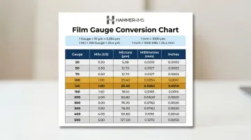
- Four units follow fixed relationships: 1 mil = 100 gauge = 25.4 microns = 0.0254 mm
- Gauge consistency matters as much as nominal value — CD and MD variation cause failures even when the average meets spec
- Measurement method determines data quality: contact micrometers for spot checks, inline scanning for live production control
- Correct gauge selection requires matching thickness to mechanical, barrier, and processing requirements — not just cost
What Film Gauge Thickness Actually Means
Film gauge is a dimensionless unit expressing the thickness of plastic film and flexible packaging materials. In the plastic film industry, 1 gauge unit equals 0.01 mils or 0.254 microns. Unlike wire gauge systems—where higher numbers indicate thinner wire—plastic film gauge increases linearly with thickness. A 200-gauge film is twice as thick as a 100-gauge film.
Gauge functions as a design specification that defines the material's physical cross-section and directly governs critical performance characteristics:
- Tensile strength and elongation — thicker films withstand higher loads before breaking
- Tear resistance — gauge affects both propagation tear and initiation tear
- Barrier performance — oxygen transmission rate (OTR) and moisture vapour transmission rate (MVTR) decrease as gauge increases
- Heat seal integrity — thicker sealant layers fill gaps at joints and corners more effectively
These performance properties make gauge a critical specification at the design stage. Gauge is set during extrusion by die gap, line speed, and draw ratio — but it's also an operational variable that drifts during production. Process disturbances such as screw surging, melt temperature variation, and die lip wear cause gauge to shift from target values. Maintaining specification compliance throughout a production run requires active monitoring and control.
Factors That Influence Gauge in Real-World Production
A film produced to a target of 80 gauge will exhibit local variation due to die lip geometry, melt flow uniformity, and cooling conditions. The gap between nominal spec and actual field performance is not a minor tolerance issue—it's the difference between a roll that runs smoothly on a form-fill-seal line and one that causes wrinkles, seal failures, and downtime.
Manufacturing inputs that determine gauge output:
- Extruder die gap setting and uniformity across the die lip
- Melt temperature, viscosity, and flow distribution
- Take-up or haul-off speed consistency
- Nip roll pressure and alignment
- Air ring performance (blown film) or quench bath temperature (cast film)
Operating conditions affect gauge consistency over a production run. Start-up transients, temperature drift in the die, line speed changes, and resin lot-to-lot viscosity differences all generate gauge variation that may not be visible without continuous measurement.
A die that heats unevenly creates systematic thick and thin bands across the web width, while extruder screw surging produces periodic thickness waves along the running direction.
In multilayer and coextruded films, individual layer gauge must be controlled in addition to total gauge. Layer ratio drift affects optical clarity, barrier performance, and sealing properties independently of the total thickness reading—making inline profiling essential for applications where layer uniformity directly affects product performance.
Film Gauge Conversion: Units, Formulas, and Reference Chart
The film industry uses four primary thickness units, often appearing simultaneously on datasheets, order forms, and equipment specs. "Gauge" and "mils" are North American conventions, "microns" (µm) is the SI metric standard used in Europe and Asia, and "millimetres" bridges both systems. This diversity creates persistent confusion in global supply chains.
Core Conversion Formulas
Gauge to mils: Divide gauge by 100
- Example: 80 gauge ÷ 100 = 0.80 mils
Mils to microns: Multiply mils by 25.4
- Example: 0.80 mils × 25.4 = 20.32 microns
Microns to millimetres: Divide microns by 1,000
- Example: 20.32 µm ÷ 1,000 = 0.02032 mm
Microns to inches: Divide microns by 25,400
- Example: 20.32 µm ÷ 25,400 = 0.0008 inches
Film Gauge Conversion Reference Table
| Gauge | Mils (US) | Microns (µm) | Millimetres (mm) | Inches |
|---|---|---|---|---|
| 20 | 0.20 | 5.08 | 0.00508 | 0.00020 |
| 30 | 0.30 | 7.62 | 0.00762 | 0.00030 |
| 40 | 0.40 | 10.16 | 0.01016 | 0.00040 |
| 50 | 0.50 | 12.70 | 0.01270 | 0.00050 |
| 60 | 0.60 | 15.24 | 0.01524 | 0.00060 |
| 75 | 0.75 | 19.05 | 0.01905 | 0.00075 |
| 80 | 0.80 | 20.32 | 0.02032 | 0.00080 |
| 100 | 1.00 | 25.40 | 0.02540 | 0.00100 |
| 120 | 1.20 | 30.48 | 0.03048 | 0.00120 |
| 150 | 1.50 | 38.10 | 0.03810 | 0.00150 |
| 200 | 2.00 | 50.80 | 0.05080 | 0.00200 |
| 250 | 2.50 | 63.50 | 0.06350 | 0.00250 |
| 300 | 3.00 | 76.20 | 0.07620 | 0.00300 |
| 400 | 4.00 | 101.60 | 0.10160 | 0.00400 |
| 500 | 5.00 | 127.00 | 0.12700 | 0.00500 |
Critical Unit Ambiguity: Mil vs Millimetre
The term "mil" causes severe international confusion. In the US, 1 mil equals exactly 0.001 inch. Outside the US, "mil" is sometimes informally used to mean millimetre. Because 1 millimetre equals 39.37 mils, confusing these units creates a nearly 40-fold thickness error—ordering what you believe is a 2-mil film and receiving a 2-mm sheet instead.
To avoid these errors in cross-border specifications, follow three practical rules:
- Always state units explicitly on every document — never assume the reader shares your convention
- For films under 250 µm (10 mils), use microns as the primary unit; ASTM D8136 defines its thin film scope at this threshold, reflecting broad industry preference for microns in this range
- For thicker materials, match the unit to the application: mils or microns for industrial and mil-spec contexts, millimetres for very thick films such as geomembranes and structural sheets
Gauge itself is generally reserved for thinner films below approximately 10 mils (250 microns). Understanding which convention applies — and stating it clearly — prevents the kind of specification errors that cause costly production rejects.
Factors That Affect Film Gauge Consistency in Production
Nominal gauge on a datasheet is a target, not a guarantee. Achieving and maintaining that target during extrusion is technically challenging because multiple interacting process variables affect the final thickness profile.
Die-Related Causes of Gauge Variation
Cross-direction (CD) gauge variation manifests as thick and thin bands running parallel to the machine direction across the web width. Primary causes include:
- Die lip wear and buildup - Material accumulation at the lip or localized erosion creates systematic CD bands that repeat from roll to roll
- Non-uniform die gap geometry - Manufacturing tolerances in the die body or lip adjustment mechanism produce baseline thickness variation
- Thermal gradients across the die face - Localised temperature differences alter melt viscosity and flow rate; a hotter zone produces a heavy-gauge band, a cooler zone produces a thin-gauge band
These die-related variations cannot be corrected by adjusting average output. They require mechanical die adjustment, cleaning, or thermal profile optimisation to resolve them.
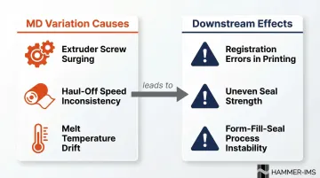
Machine-Direction Variation
Machine-direction (MD) gauge variation occurs along the running direction of the film and is driven by time-dependent process instabilities:
- Extruder screw surging - Feed instability or melt pressure fluctuations create periodic thickness waves
- Haul-off speed inconsistency - Drive system variations or tension control issues produce longitudinal gauge variation
- Melt temperature or viscosity changes - Temperature controller drift or resin lot changes alter flow characteristics
MD variations are particularly problematic for laminating, printing, and form-fill-seal applications where consistent tension and uniform thickness are assumed. A film with significant MD variation will cause registration errors, uneven seal strength, and downstream process instability.
Environmental and Duty-Cycle Effects
Extended production runs introduce additional sources of gauge drift:
- Ambient temperature changes affect cooling rates and frost line height in blown film, altering draw-down and final gauge
- Die temperature creep occurs during long runs as thermal mass equilibrates, shifting nominal gauge without operator intervention
- Humidity effects on hygroscopic resins (nylon, EVOH) can alter melt viscosity and flow behaviour
These slow, cyclical variations require automated profile control or periodic manual adjustment to maintain specification limits across extended production runs.
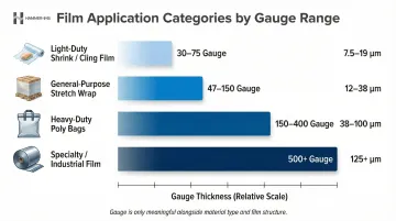
Typical Gauge Ranges by Film Type and Application
Gauge selection is application-driven. The appropriate thickness for a given use case is determined by the required combination of mechanical performance, barrier properties, ease of processing, and cost. Below are typical gauge ranges for common film categories.
| Film Category | Typical Gauge Range | Micron Equivalent | Common Applications |
|---|---|---|---|
| Light-Duty Shrink/Cling | 30–75 Gauge | 7.6–19.0 µm | Retail display shrink, food wrap |
| General-Purpose Stretch | 47–150 Gauge | 11.9–38.1 µm | Pallet wrapping (hand and machine) |
| Heavy-Duty Poly Bags | 150–400 Gauge | 38.1–101.6 µm | Industrial liners, hardware packaging |
| Specialty/Industrial | 500+ Gauge | >127.0 µm | Geomembranes, medical barrier films |
A 100-gauge polyolefin shrink film and a 100-gauge LDPE stretch film represent the same physical thickness but very different functional performance. Gauge is only meaningful when interpreted alongside material type, structure (monolayer vs multilayer), and orientation (cast vs blown). These ranges are a starting point — not a substitute for material-specific specification.
Converting GSM to Thickness
Beyond gauge and microns, some applications — particularly nonwovens and technical textile films — specify thickness using grams per square metre (GSM). Converting between this weight-based unit and a physical thickness requires one additional input: material density.
Thickness (µm) = GSM ÷ Density (g/cm³)
Without the exact resin blend density, a GSM value cannot be reliably converted to a gauge specification.
For example, a 50-GSM film made from LDPE (density ~0.92 g/cm³) will measure thicker than a 50-GSM film made from polypropylene (density ~0.90 g/cm³) — even though both weigh the same per unit area. The same weight, in other words, does not mean the same thickness.
How Film Gauge Is Specified, Measured, and Validated
Film gauge appears on design specs (datasheets, purchase orders, engineering drawings) and in quality records (incoming inspection, in-process monitoring, final lot certification). The measurement method used determines whether these two sets of numbers are actually comparable.
Specification and Documentation
Film gauge is typically specified as a nominal value with a tolerance range on product datasheets and purchase orders. A common specification might read "80 gauge ±10%" or "20.3 µm ±2.0 µm." Tolerance range varies significantly between commodity packaging films and precision industrial films. Tighter tolerances require better process control, more frequent monitoring, and potentially slower line speeds—all of which increase production cost.
Standard measurement references:
- ASTM D6988 - Guide for determination of thickness of plastic film using a dead-weight contact micrometer
- ASTM D8136 - Standard test method for determining plastic film thickness and variability using non-contact capacitance gauge (scope: 2.5 to 250 µm)
- ISO 4593 - Determination of thickness of plastics film or sheeting by mechanical scanning (international equivalent to ASTM methods)
Measurement and Verification Methods
Offline Measurement: Contact Micrometers
A calibrated contact micrometer (dead-weight or bench-type) is the traditional method for spot-checking film gauge. The operator places the film between the micrometer anvil and measuring foot, and a known dead weight applies consistent pressure to compress the sample.
Limitations of contact micrometers:
- Captures thickness at a single location only, missing CD and MD profiles entirely
- Compresses thin films by up to 0.03 mils under physical pressure, creating artificial thickness reduction
- Produces results that vary with operator technique and sample handling
- Misses gauge bands and localised defects that spot checks at edges and centre cannot detect
According to industry data, a standard micrometer has a precision of ±0.05 mils. On a 0.5-mil film, this yields a ±10% measurement error—unacceptable for quality-critical applications.
Inline Continuous Gauging: Production-Grade Standard
Inline scanning systems mount sensors on a traversing frame that moves across the web, building a real-time thickness profile across the full width. These systems enable:
- Real-time detection of gauge bands, die lip wear, and process drift across full CD and MD profiles
- Closed-loop feedback to die lip actuators or haul-off speed controls, correcting gauge deviation automatically
- 100% material coverage, eliminating sampling error and ensuring every metre of film meets specification
- Non-contact measurement that avoids compression bias and material damage
One implementation of this approach is Hammer-IMS M-Ray technology, which uses electromagnetic millimetre-wave technology at 60 GHz to measure film thickness without physical contact.
Unlike nuclear-source gauges (krypton-85 or strontium-90 beta gauges), M-Ray removes the need for radiation licensing, eliminates operator exposure risks, and avoids radioactive waste disposal requirements—while maintaining high-resolution continuous measurement across the full web width.
Common Misinterpretations and Consequences of Gauge Deviation
Treating Nominal Gauge as Actual Gauge
Many buyers and processors assume the labelled gauge is uniform throughout a roll. In reality, gauge varies within every roll due to process instabilities and die geometry. The labelled value represents a target average, not a guarantee of uniformity. Undersized gauge in any region can cause localised failure in high-stress applications—pallet loads breaking through thin spots during transport, seal failures at weak points in flexible pouches, or barrier compromise in pharmaceutical packaging.
Ignoring Cross-Direction Profile Variation
Even when average gauge meets specification, a film with significant CD variation (thick edges and thin centre, or vice versa) causes downstream problems:
- Creates tension imbalances when unwinding, causing wrinkles that jam printing or laminating equipment
- Produces weak seals at thin spots and excess material use at thick spots, making seal strength unpredictable
- Allows higher gas or moisture transmission through thin bands, shortening product shelf life
- Disrupts web tracking on form-fill-seal lines, causing print-to-cut misalignment
Research shows that inconsistent film thickness alters heat transfer rates at sealing jaws. If the sealant layer is too thin, it fails to fill gaps at joints and corners, leading to pinholes and leaks. Conversely, excessive thickness can cause incomplete melting and weak adhesive bonds.
Average gauge measurement alone is insufficient for quality-critical applications. Full CD profile data is required to detect and correct these systematic variations.
Applying Gauge Spec from One Film Type to Another Without Adjustment
A 100-gauge specification for polyolefin shrink film and a 100-gauge specification for LDPE stretch film represent the same physical thickness—but very different functional performance. These are not interchangeable specs.
Downgauging a multilayer structure from 3.0 mils to 2.7 mils to reduce weight can cause the film to fail barrier, tear resistance, and stiffness specifications unless the resin architecture is simultaneously upgraded.
Gauge must always be evaluated in context:
- Material type — LDPE, LLDPE, HDPE, PP, PET, nylon, and EVOH each deliver different mechanical and barrier properties at the same gauge
- Film structure — monolayer, multilayer, and coextruded constructions translate total gauge into performance differently
- Orientation — cast, blown, and biaxially oriented films produce different strength and optical characteristics at identical gauge
Frequently Asked Questions
How thick is a 30 gauge or 100 gauge film?
30 gauge equals 0.30 mils, 7.62 microns, or 0.00762 mm. 100 gauge equals exactly 1.0 mil, 25.4 microns, or 0.0254 mm. These are physical thickness values that apply regardless of film material type.
How do I compare film thickness in mils vs gauge to determine which is thicker?
Divide gauge by 100 to get mils. For example, 150 gauge = 1.5 mils, and 80 gauge = 0.80 mils. Once both films are expressed in the same unit, direct comparison is direct. A higher number in either unit always means a thicker film.
What is the difference between a micron and a mil in film thickness measurement?
A mil is 1/1000th of an inch (a US customary unit), while a micron (µm) is 1/1000th of a millimetre (an SI metric unit). 1 mil equals 25.4 microns. Be aware that "mil" is sometimes misread as "millimetre" in non-US contexts, creating a 40-fold error. Always specify units explicitly.
Why does film gauge vary across a roll or production run?
Gauge variation stems from die lip wear, thermal gradients, melt flow non-uniformity, cooling inconsistencies, and line speed changes. While normal, it must stay within specification limits. Inline scanning systems detect deviations in real time, enabling process correction before defective material accumulates.
What standards govern the measurement of plastic film gauge?
ASTM D6988 and ASTM D8136 are the primary US standards; ISO 4593 is the international equivalent. Compliant measurement uses a calibrated dead-weight micrometer (D6988) or a validated non-contact capacitance gauge (D8136), with D8136 preferred for films under 250 µm to eliminate compression bias.
How can I measure film gauge thickness continuously during production?
Inline scanning gauges measure cross-direction and machine-direction thickness profiles in real time during production, enabling closed-loop process correction. Contactless technologies like millimetre-wave gauging (such as Hammer-IMS M-Ray) eliminate the need for nuclear sources whilst providing high-resolution continuous measurement without contact with the film surface, with no radiation source licensing or safety officer requirements.