Introduction
Corrosion hidden beneath insulation boards is one of the most dangerous failures in industrial manufacturing. Unlike surface defects, internal degradation develops silently — moisture reacts with metallic facers, foam cores lose density, and structural integrity erodes with no outward sign until failure occurs.
Traditional inspection methods compound the problem. Each common approach carries significant drawbacks:
- Visual inspection requires removing insulation, halting production, and often destroying the sample
- X-ray techniques involve ionising radiation, triggering strict regulatory burdens — licensing, shielding, dosimetry, and certified Radiation Safety Officers
- Ultrasonic testing demands direct surface contact and misses non-localised corrosion patterns
C-Ray analysis offers a non-invasive alternative. This electromagnetic wave-based scanning technique allows manufacturers to detect internal corrosion, moisture pockets, and density anomalies in-line, at production speed, without removing insulation or disrupting output. For insulation board manufacturers facing warranty claims, field failures, and rising quality control costs, C-Ray enables 100% inspection coverage without radioactive sources or production slowdowns.
TLDR
- C-Ray analysis uses electromagnetic scanning to identify corrosion and material anomalies within insulation boards without ionising radiation or physical contact
- Detects moisture ingress, density variations, and metallic degradation that compromise thermal performance and structural integrity before surface signs appear
- Works by measuring signal attenuation, phase shift, and time-of-flight changes caused by variations in material composition
- Eliminates radioactive sources, safety protocols, and production stoppages required by traditional X-ray and ultrasonic methods
- Hammer-IMS provides non-nuclear M-Ray measurement systems that support contactless, in-line quality control at full production speed
What Is C-Ray Analysis?
"C-Ray" is not a standardised NDT term recognised by authoritative industry glossaries. In formal radiography contexts, "CR" denotes Computed Radiography, which replaces traditional X-ray film with reusable photostimulable phosphor imaging plates. In the context of non-ionising wave-based scanning for insulation boards, "C-Ray analysis" functions as a proprietary or vendor-specific label for electromagnetic millimetre-wave (MMW) or terahertz (THz) imaging systems.
These systems operate within specific frequency ranges:
- Microwave: 300 MHz to 30 GHz (wavelengths 1 m to 10 mm)
- Millimetre-Wave: 30 GHz to 300 GHz (wavelengths 10 mm to 1 mm)
- Terahertz: 0.1 THz to 10 THz (wavelengths 3 mm to 30 µm)
Primary Applications in Manufacturing
C-Ray analysis serves multiple quality assurance functions during and after production:
- Verifies thickness and density across the full panel width at production speed
- Identifies internal voids or moisture zones that may accelerate corrosion or degrade thermal performance
- Maps grammage uniformity to catch manufacturing inconsistencies before panels leave the line
- Performs post-production integrity checks for high-value batches or quality audits
Comparison to Other Wave-Based Methods
Each wave-based inspection method has a different fit for insulation materials. The table below shows where C-Ray sits relative to the alternatives:
| Method | Radiation Type | Contact Required | Works on Foam/Mineral Wool? |
|---|---|---|---|
| X-ray | Ionising | No | Yes, with safety protocols |
| Ultrasonic | Sound waves | Yes (couplant needed) | Limited — surface texture interferes |
| C-Ray (MMW/THz) | Non-ionising | No | Yes — material is highly transparent |
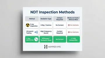
The reason C-Ray performs well on insulation boards comes down to dielectric permittivity — a measure of how much a material absorbs wave energy. Low-density polymer foams (PIR, EPS, XPS) and mineral wool absorb very little millimetre-wave or terahertz radiation, so the signal passes through cleanly. This material transparency makes C-Ray a practical choice where X-ray safety constraints or ultrasonic couplant requirements create operational friction.
Why Detecting Corrosion in Insulation Boards Is a Hidden Threat
Internal corrosion in insulation boards develops invisibly—surface indicators rarely appear until structural damage is already widespread. Moisture ingress reacts with aluminium foil facers to create poultice corrosion—an oxygen-starved environment that initiates metallic degradation without surface indicators. Density collapse within polyisocyanurate foam cores proceeds silently, reducing compressive strength and wind-uplift resistance. By the time these defects manifest as visible facer disbondment or structural failure, entire production batches may be compromised.
The Cost Impact of Undetected Defects
The financial consequences add up fast. Key data points illustrate the scale:
- Moisture in insulation layers can increase thermal transmittance by a factor of 2.2, effectively halving panel insulation performance
- Moisture-damaged roof insulation remediation costs approximately $4.45 per square foot for full removal and replacement
- Water damage claims average $11,420 per incident, occurring at 1.50 claims per 100 policies
For manufacturers, the impact extends well beyond warranty claims. Rejected batches trigger rework costs, storage losses, and customer complaints. Field failures damage brand reputation and jeopardise contract renewals—while energy performance losses erode the core value proposition that drives purchasing decisions.
Conditions That Create Internal Corrosion Risk
Insulation boards become susceptible to internal corrosion under specific conditions:
- Metallic facer materials: Foil-faced polyisocyanurate panels are particularly vulnerable, as aluminium facers undergo galvanic corrosion when coupled with different metals in the presence of water
- Moisture trapped during manufacturing: Water from laminating adhesives or environmental exposure becomes trapped in the fibreglass matrix or porous foam, creating the electrolyte necessary for corrosion
- Temperature cycling in storage: Condensation forms when panels move between different temperature zones, introducing moisture at interfaces
- Improper sealing: Knit-line grooves in polyisocyanurate foam can leave facers unadhered, creating pathways for moisture ingress and reducing bond strength
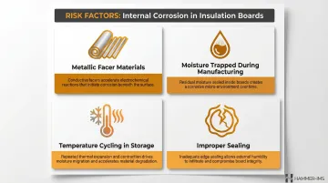
Recognising these risk factors allows manufacturers to target inspection resources where they're most needed and adjust process parameters before defects propagate through production runs.
How C-Ray Analysis Detects Corrosion – Step by Step
Step 1 – Define the Inspection Objective
Operators must specify whether the analysis targets full-panel grammage uniformity, facer corrosion at metal-foam interfaces, internal moisture pockets, or localised density anomalies before configuration begins. Each objective requires different calibration settings, scan parameters, and signal interpretation protocols.
Poorly defined objectives are the most common reason C-Ray results are misinterpreted or acted upon incorrectly. A scan configured to detect gross density variations will miss subtle moisture ingress at facer interfaces. Conversely, high-sensitivity moisture detection may flag harmless manufacturing variations as defects, triggering unnecessary line stoppages.
Step 2 – Configure the Scanning System
The C-Ray scanner is positioned and calibrated for the specific insulation board type—polyisocyanurate with foil facers, expanded polystyrene without facers, or mineral wool with glass tissue. Configuration covers three core parameters:
- Gap settings: the standoff distance between sensor and material surface
- Beam area: the spatial resolution governing how finely the scan resolves anomalies
- Reference baselines: signal values from defect-free panels that define "normal" for that board type
Sensors positioned above or below the conveyor operate continuously, capturing data on every panel without physical contact that could damage surface finishes or introduce contamination.
Step 3 – Transmit and Capture Signal Data
The C-Ray beam passes through the insulation board. Changes in the return signal—or in through-transmission mode, the transmitted signal captured on the opposite side—indicate variations in material composition.
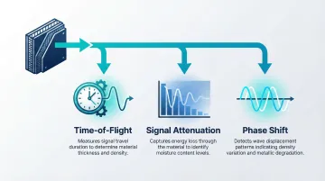
Three signal parameters provide detection information:
- Time-of-flight: The delay between transmission and reception reveals material thickness and density
- Signal attenuation: Absorption of electromagnetic energy indicates moisture content, as liquid water has a significantly higher absorption coefficient (~230 cm⁻¹ at 1 THz) than dry polymers (<10 cm⁻¹)
- Phase shift: Changes in wave phase correlate with density variations and metallic degradation at interfaces
Unlike radioactive methods, signal capture does not require shielding protocols, dosimetry monitoring, or evacuation zones. Millimetre-wave and terahertz radiation are strictly classified as non-ionising electromagnetic radiation, meaning operators can work alongside scanning equipment without safety restrictions.
Step 4 – Process and Map the Results
Raw signal data is processed into spatial maps or density profiles across the panel width. Software algorithms then identify high-risk zones where corrosion precursors—moisture, voids, density loss—are concentrated.
Visualisation tools display these anomalies as colour-coded heat maps, cross-sectional profiles, or statistical distributions that highlight deviations from specification.
Uniformity tools provide more than average values. They reveal whether density variations are randomly distributed (suggesting process instability) or concentrated in specific zones (indicating equipment wear or calibration drift). This spatial information enables targeted remediation rather than broad, inefficient process changes.
Step 5 – Act on the Findings
Results only improve quality when they feed directly into production decisions through defined protocols:
- Flagging panels for rejection when anomalies exceed specification limits
- Triggering closed-loop process adjustments to blending ratios, line speed, or curing parameters based on real-time feedback
- Scheduling targeted maintenance on specific equipment zones correlated with defect locations
Integration with PLCs, SCADA, or OPC-UA interfaces closes the feedback loop automatically, allowing corrective actions to execute within seconds of a defect being detected rather than waiting for manual review.
C-Ray vs. Traditional Corrosion Detection Methods
Visual Inspection
Visual inspection captures only surface-level information. Detecting internal corrosion requires removing insulation, making it destructive, labour-intensive, and incompatible with in-line production environments. Subsurface degradation — the most operationally damaging kind — goes undetected entirely.
X-Ray and Computed Radiography
X-ray systems deliver high-resolution imaging of internal structures and are highly effective for smaller panels or laboratory analysis. However, they involve ionising radiation that creates significant regulatory burdens in production environments.
Under NRC 10 CFR Part 170, industrial radiography licensing fees range from $11,600 for 1–5 locations to $19,300 for more than 20 locations. Operations also require certified Radiation Safety Officers with 2,000 hours of hands-on experience, continuous personnel dosimetry monitoring, and engineered shielding enclosures.
Ultrasonic Testing (UT)
Ultrasonic testing requires direct surface contact or plug removal to apply couplant and achieve acoustic coupling. It captures localised data points rather than full-width profiles, making it impractical for continuous production environments. High attenuation in foam and air-filled structures further limits effectiveness for insulation board applications.
Pulse Eddy Current (PECT)
Pulse eddy current is non-invasive and contactless, but restricted to carbon and low-alloy steel substrates. It cannot penetrate dielectric insulation materials, making it incompatible with polymer foam boards or mineral wool.
Key Advantages of C-Ray Analysis
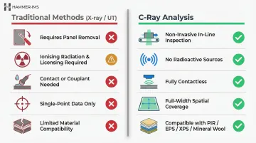
Compared to these alternatives, C-Ray analysis offers:
- Inspects panels without removal — preserves integrity and keeps lines running
- Requires no radioactive sources, eliminating licensing fees, shielding costs, and dosimetry
- Integrates contactlessly into production lines without reducing throughput
- Scans the full panel width, capturing spatial variation across the entire surface
- Compatible with PIR, EPS, XPS, mineral wool, and foil-faced panel types
Limitations to Consider
C-Ray analysis has practical constraints operators should understand:
- Aluminium foil facers completely reflect millimetre-wave and terahertz signals, blocking through-transmission; reflection-mode time-of-flight measurements are required at the foam-metal interface
- Detection sensitivity depends on accurate baseline calibration against defect-free reference material — poor calibration directly degrades performance
- Deep metallic pit corrosion in thick panels may require supplementary X-ray confirmation
Cost and Compliance Implications
Non-nuclear, non-invasive inspection methods reduce the total cost of quality control. Traditional X-ray systems incur ongoing costs for dosimetry, shielding maintenance, and regulatory compliance. C-Ray systems avoid these expenses entirely while maintaining data acquisition rates up to 20 kHz for in-line scanning at production speeds, which supports faster return on investment at production-line throughput.
How Hammer-IMS Can Help
Hammer-IMS provides advanced, non-nuclear quality and process control measurement systems specifically designed for insulation board manufacturers. The company's M-Ray technology—a patented electromagnetic millimetre-wave measurement system—operates in the 30–300 GHz frequency range, delivering contactless, in-line inspection without ionising radiation or safety protocols.
Key Capabilities for Corrosion and Defect Detection
Hammer-IMS systems address the core challenges of insulation board quality control:
- Multiple sensor heads span the full material width, delivering near 100% coverage and catching localised anomalies that single-point systems miss
- Continuous cross-machine profiling captures thickness, basis weight, and density variations across the entire panel in real time
- Software visualisation maps spatial distributions of internal anomalies—not just averages—so operators can pinpoint where adjustments are needed
- Direct PLC integration enables automatic line corrections when anomalies are detected, rather than waiting for downstream quality checks
Hammer-IMS has deployed these systems across XPS, EPS, GPS, and PUR insulation board lines—covering polyurethane, polystyrene, and mineral wool production—with no radioactive emission licences or specialist operator certifications required.
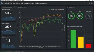
Connectivity 3.0 Software Platform
The Connectivity 3.0 software serves as the central hub for Hammer-IMS measurement systems, enabling remote monitoring, data logging, and analytics integration. Quality teams can track corrosion risk trends over time rather than reacting only to failures. The platform provides:
- Graphical and numerical visualisations of physical parameters in continuous production
- Real-time FFT analysis for monitoring periodic behaviour patterns that indicate equipment wear
- Industry-specific KPI calculations including Uniformity Index and Coefficient of Variation
- Automatic calibration functionality in air or using reference materials, maintaining accuracy throughout production runs
The result is a system that flags density anomalies and corrosion-related irregularities at the point of production—before non-conforming panels move further down the line.
Frequently Asked Questions
What is C-Ray analysis and how does it differ from standard X-ray inspection?
C-Ray analysis uses electromagnetic millimetre-wave or terahertz scanning to detect internal material anomalies without ionising radiation, whereas standard X-ray uses radioactive sources requiring shielding, dosimetry, and certified safety officers. C-Ray operates contactlessly at production speed without those safety protocols.
Can C-Ray analysis detect corrosion without removing the insulation?
Yes — C-Ray is entirely non-invasive and contactless, inspecting through the board without removal or production stoppage. Measured changes in attenuation, phase shift, and time-of-flight pinpoint internal density variations, moisture zones, and metallic degradation that signal corrosion risk.
What types of insulation boards can be inspected with C-Ray analysis?
C-Ray systems inspect polyisocyanurate (PIR), expanded polystyrene (EPS), extruded polystyrene (XPS), mineral wool, and foil-faced panels. Calibration requirements differ by material type and facer composition; dense metallic facers require reflection-mode scanning rather than through-transmission.
How does C-Ray analysis compare to ultrasonic testing (UT) for insulation boards?
Ultrasonic testing requires direct surface contact or plug removal and captures only localised data points, while C-Ray provides non-contact, full-width scanning across the entire panel. For in-line production environments, that broader area coverage matters — no contact, no slowdown.
Is C-Ray technology safe to operate in a live production environment?
Yes. Non-nuclear millimetre-wave systems require no radiation safety zones, shielding, dosimetry, or specialist handling protocols. The non-ionising electromagnetic radiation is inherently safe, making these systems suitable for continuous in-line use alongside production staff.
How often should insulation boards be inspected for corrosion using C-Ray analysis?
In-line systems support continuous 100% inspection at production speed, eliminating the need for periodic sampling. Where offline checks are used instead, frequency should reflect material type, storage conditions, and facer vulnerability.