Introduction
Consistent material thickness is a fundamental quality requirement across industries—from textiles and plastics to metals and nonwovens. Even small deviations can trigger downstream failures or generate costly scrap. In European flat steel production alone, 32% of liquid metal never makes it into a final product, with 60% of that material scrapped during manufacturing due to quality issues including thickness variation.
Inline (in-process) thickness measurement addresses these blind spots by replacing periodic spot-checks with continuous, real-time monitoring. But this shift introduces its own set of technical challenges: sensor alignment errors, thermal expansion of frames, material movement within the measurement gap, and sensor-material compatibility issues.
Left unmanaged, these factors erode measurement accuracy and lead to out-of-tolerance product, wasted material, and costly downstream failures. This article breaks down each challenge and the practical approaches that resolve them.
Key Takeaways
- Inline measurement monitors thickness continuously, catching deviations that manual spot-checks miss
- Key challenges: sensor misalignment, thermal frame expansion, web flutter, and material compatibility
- Unaddressed errors compound across production runs, causing scrap and customer rejections
- Solutions combine system-level calibration, active thermal compensation, and sensor technology matched to material type
- Long-term accuracy depends on automated calibration schedules and real-time data trending
Common Challenges in Inline Thickness Measurement
Inline thickness measurement fails in predictable ways — sensor misalignment, thermal drift, web movement, and material incompatibility each introduce errors that compound under real production conditions. Understanding each mechanism is the first step toward controlling them.
Sensor Alignment and Synchronization
When measuring material thickness from both sides in free space, opposing sensors must be precisely co-aligned so their measuring spots coincide through the full range of material movement. Any offset, tilt, or timing mismatch between the two sensors introduces cumulative error.
Research demonstrates the scale of alignment-induced errors: a sensor offset of 1 mm combined with an inclination of just 2° produces an effective error of 35 µm at a 10 mm target thickness. At the same thickness, the error increases to 41 µm when angular deviation grows. Angular misalignment creates cosine error, a recognized metrology problem that degrades dimensional measurement accuracy.
Asynchronous capture risk is equally critical. If the material is vibrating or oscillating in the gap and the two sensors are not triggered simultaneously, one sensor captures a different material position than the other—artificially inflating thickness readings. For a target oscillating vertically by 1 mm at 20 Hz, a 1 ms difference in capture time produces a measurement error of 125 µm.
Thermal Expansion and Frame Instability
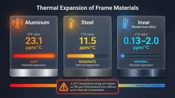
The mechanical frame holding the sensors is the reference for the entire gap calculation. Temperature fluctuations cause that frame to expand or contract—shifting the sensor gap even when actual material thickness remains constant. A temperature swing of just 5°C can cause an effective gap change of up to 20 µm.
Without active compensation, a 25°C temperature change can be perceived by the system as an almost 400 µm change in material thickness—an error large enough to render a production run out of spec.
The problem is asymmetric in O-frame configurations — heat rises, so the upper sensor drifts more than the lower one. Low-expansion frame materials help, but they are not sufficient alone without a dedicated compensation strategy.
Frame material choice significantly affects baseline stability:
| Material | Thermal Expansion Coefficient |
|---|---|
| Aluminum | 23.1 ppm/°C |
| Steel | 11.5 ppm/°C |
| Invar (nickel-iron alloy) | 0.13–2.0 ppm/°C (heat treatment dependent) |
Material Movement and Web Flutter
Roll-to-roll production processes—common in films, nonwovens, textiles, and foams—subject material to speed changes, start-stop cycles, and tension variations that cause the web to flutter or shift vertically within the measurement gap. If the sensor measuring range does not fully contain this movement, one sensor may temporarily lose the target, producing false readings or data dropouts.
Experimental measurements on a 127 µm thin web identified distinct resonant vibration peaks at 17.6 Hz and 22.4 Hz. Any movement of the probe mounting system or material vibration—even movement too small to be seen—will skew sub-micron measurement results.
Line speed changes during start and stop phases are the highest-risk moments for measurement instability. Overlapping sensor measurement ranges are essential to capture these events reliably.
Sensor-Material Compatibility
Not all sensing technologies work equally well on all materials. Optical methods can struggle with:
- Highly reflective metallic surfaces
- Absorptive black materials
- Textured or oily surfaces
- Very soft, compressible substrates like foam or needlepunch nonwovens
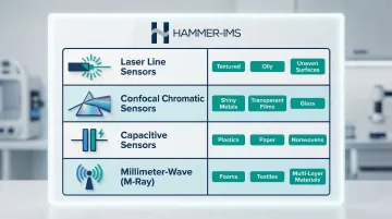
Each material type demands a different sensor approach or signal processing strategy:
- Laser triangulation — tilt compensation and surface averaging suit textured or uneven materials
- Confocal chromatic sensors — highest precision on shiny metallic surfaces
- Millimeter-wave (M-Ray) technology — operates at 30–300 GHz for contactless, micrometer-accurate measurement across widths of 5+ metres; no coupling medium required, making it well-suited for soft, multi-layer, or compressible materials
Traditional nuclear or isotopic gauges remain common in metals processing but introduce significant regulatory and operational burdens. US NRC regulations under 10 CFR § 31.5 require general licenses, mandatory leak tests, and strict record retention for any commercial use.
In the EU, the cost picture is steeper: nuclear gauges carry licensing fees exceeding €7,400, mandatory periodic inspections, and total lifetime costs exceeding €300,000 per sensor—limiting flexibility whenever product changeovers require recalibration.
What Happens When Inline Measurement Errors Go Unaddressed
Out-of-tolerance material that passes through undetected results in large batches of scrap or rework. Because errors compound across a full production run, even a small but consistent offset error can mean an entire roll or coil fails customer specification.
In one documented case, thickness disputes caused a bag-maker to reject 10% to 15% of film shipments. Over a six-month period, this cost the film producer $15,000 to $20,000 per month and the converter approximately $100,000 total. In linear low-density polyethylene (LLDPE) extrusion, average losses per stoppage are around 6.7%.
Those losses extend beyond the production floor. Customers receiving off-spec material may issue returns, chargebacks, or quality complaints — and in regulated sectors such as medical devices or automotive, thickness deviations can trigger safety non-conformances or full production holds.
The consequences in regulated industries can be severe. FDA Recall Z-1636-2010 was issued for medical device tibial inserts due to thickness nonconformances. A separate recall involved endotracheal tubes with smaller-than-expected diameter, carrying risk of patient underventilation.

Warning Signs You're Experiencing Measurement Drift
Operators often blame material variability when readings start shifting — but the gauging system itself is frequently the source. Drift tends to build slowly, making it easy to miss until the damage is already in the product.
Watch for these patterns:
- Readings that shift throughout a shift as factory temperature rises, then return to baseline after shutdown
- Recurring edge-of-range readings or dropout events during line start-up and speed changes
- Customer complaints or incoming inspection rejections that rise without any visible production defects to explain them
How to Overcome Inline Thickness Measurement Challenges
Effective solutions work across three layers: system-level calibration establishes accuracy, active thermal compensation controls environmental influence, and real-time feedback closes the loop between measurement and process control.
System-Level Calibration Over Sensor-Level Accuracy
There's a critical distinction between individual sensor accuracy (as stated on a datasheet) and combined system accuracy. Because each sensor in a dual-sensor setup has its own linearity deviation, the system must be calibrated as a whole using a certified gauge block of known thickness placed in the measurement path. This allows the system to store a combined linearization correction rather than relying on individual sensor specifications.
Regular automated returns to the calibration position allow the system to detect and correct for changes in the sensor gap caused by thermal drift or mechanical wear—without requiring manual intervention. ISO 10012:2026 introduces a risk-based approach to calibration interval optimization, utilizing drift analysis and statistical methods to balance calibration costs against the risk of measurement errors.
Active Thermal Compensation
Effective thermal compensation goes beyond choosing a low-expansion frame material. It requires continuously measuring the sensor gap itself — using, for example, a dedicated pair of stable reference sensors mounted on the frame. Any expansion or contraction is then fed into the thickness calculation as an active correction, not simply ignored.
Periodic automated calibration checks against a certified reference block further reinforce thermal compensation, catching residual drift that passive frame design alone cannot eliminate.
Matching Sensor Technology to Material Type
The correct sensor technology depends on material surface properties, thickness range, and process conditions:
Laser line sensors offer tilt compensation and surface averaging — particularly useful for textured or oily materials where single-point sensors produce noisy readings.
Confocal chromatic sensors deliver the highest precision on shiny metallic surfaces and can measure transparent materials like glass or clear films with micrometer accuracy by evaluating multiple reflection peaks.
Capacitive sensors are well-suited for non-conductive materials such as plastic film, nonwovens, paper, coatings, and adhesives.
Millimeter-wave technologies such as Hammer-IMS's M-Ray are designed for soft, compressible, or multi-layer materials — nonwovens, foams, and technical textiles — where optical sensors may compress or reflect unpredictably. Unlike isotopic gauges, M-Ray requires no radiation safety zones, no material-type recalibration, and carries no regulatory compliance overhead, which simplifies product changeovers considerably.
Real-Time Feedback and Closed-Loop Process Control
Inline measurement only delivers its full value when measurement data is connected back to the production process in real time. Systems equipped with closed-loop control can automatically signal die adjustments, calender gap corrections, or coating weight changes before an out-of-tolerance condition produces scrap.
Remote connectivity and data logging capabilities (such as Hammer-IMS Connectivity 3.0) enable operators and process engineers to monitor thickness profiles across the web width, track trends over time, and identify the onset of process drift before it escalates— shifting the system's role from passive inspection to active process management.
Tips for Long-Term Measurement Performance and Control
Initial calibration gets your system running — but keeping it accurate over months and years takes deliberate process habits. These four practices are where most facilities either stay ahead of drift or fall behind it:
- Schedule calibration checks at defined production intervals, not only at line startup, so thermal and mechanical drift is caught before it reaches your output
- Build trend review into shift handover routines so gradual drift surfaces through data patterns rather than downstream quality failures
- Maintain a documented record of calibration offsets over time; a systematic upward or downward trend in correction values is an early indicator of sensor degradation, frame fatigue, or mounting wear requiring service
- When evaluating sensor or system upgrades, test total system accuracy under real factory conditions — temperature variation, vibration, surface irregularity — rather than relying on laboratory datasheet figures alone
Conclusion
Each challenge covered in this guide — sensor alignment, thermal compensation, material compatibility, calibration strategy — has established engineering solutions. When these are implemented together as a coherent system, they deliver measurement accuracy that offline sampling simply cannot match.
The cost of ignoring these challenges — in scrap, rework, and downstream quality failures — far exceeds the investment in a well-configured inline measurement system. Non-nuclear, contactless technologies such as millimeter-wave sensing have since resolved the practical barriers that once slowed adoption, giving manufacturers across plastics, textiles, steel, and composites a viable path to continuous, process-integrated quality control.
Frequently Asked Questions
What are the most common challenges with inline thickness measurement?
Four technical challenges dominate inline thickness measurement deployments:
- Sensor alignment — opposing sensors must be co-aligned and triggered simultaneously
- Thermal frame expansion — temperature shifts change the reference gap, distorting readings
- Web flutter — material movement causes vertical position changes within the measurement gap
- Sensor-material compatibility — sensor technology must match surface properties and material type
How does temperature affect inline thickness measurement accuracy?
As the mechanical frame expands or contracts with temperature, the reference gap shifts — producing apparent thickness errors even when the material itself hasn't changed. A 5°C swing can cause a 20 µm gap change; a 25°C change can register as a 400 µm error without compensation. Active thermal compensation or automated calibration checks are required to correct this.
What is the difference between single-sided and dual-sided inline thickness measurement?
Single-sided measurement uses a known datum surface (such as a roller or reference plate) as one reference point, while dual-sided measurement captures the material in free space between two opposing sensors. Dual-sided is more accurate for true material thickness but introduces additional alignment and synchronization challenges since both sensors must be precisely co-aligned and triggered simultaneously.
Why is non-nuclear thickness measurement preferred over traditional isotopic gauges?
Non-nuclear systems eliminate radiation safety zones, licensing requirements, and material-specific recalibration — reducing operational complexity and disposal concerns significantly. Nuclear gauges carry regulatory burdens and lifetime costs that can exceed €300,000 per sensor, making non-nuclear alternatives the practical choice for most modern production environments.
How often should inline thickness measurement systems be calibrated?
Calibration frequency depends on thermal stability and production cycle length. Best practice is to run automated checks against a certified reference block at regular intervals throughout each shift, not only at startup. Risk-based strategies use drift analysis to set optimal intervals, reducing unnecessary downtime without sacrificing accuracy.
What industries rely most on inline thickness measurement?
Primary industries include textiles and nonwovens, plastic films and sheets, metal strip processing (cold-rolling mills), foam and insulation production, battery electrode manufacturing, and construction materials such as gypsum board and XPS insulation. In each of these sectors, inline thickness control directly impacts product quality, material yield, and downstream performance.