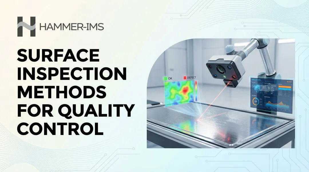
Introduction
A surface defect that slips past production and reaches the customer doesn't cost ten times more to fix — it can cost a hundred times more. When defects escape detection until final inspection or end-of-line checks, manufacturers absorb full processing costs on scrapped material, lose production capacity to rework, and face customer returns that trigger warranty claims and reputational damage. The 'Rule of Ten' captures this precisely: defect correction costs multiply tenfold at each production stage, so a $1,000 fix during production becomes a $100,000 problem once it reaches the customer.
Inline surface inspection solves this by embedding quality control directly into the production process. Unlike periodic sampling or end-of-line checks, inline systems monitor every meter of material continuously, detecting anomalies the moment they occur.
This article covers the core techniques manufacturers use — from optical cameras to millimeter-wave sensors — and the measurable business benefits that follow when defects are caught at the source.
Key Takeaways
- Inline inspection monitors surfaces continuously during production, catching defects before additional processing costs accumulate
- Key techniques include line scan cameras, laser profilometry for 3D measurement, and M-Ray non-contact electromagnetic sensors for soft and compressible materials
- Early defect detection delivers 70–85% scrap reduction, real-time closed-loop process correction, and 100% coverage versus statistical sampling
- Textiles, nonwovens, plastics, and automotive manufacturers use inline inspection to prevent costly recalls, warranty claims, and customer rejections
What Is Inline Surface Inspection?
Inline surface inspection integrates measurement and detection sensors directly into moving production lines, enabling continuous evaluation of surface characteristics without stopping or slowing production.
Sensors positioned at fixed points along the line capture data as material moves past, analyzing thickness uniformity, roughness, coating consistency, visible defects, and geometry on every unit or metre produced.
Optical, electromagnetic, or laser sensors scan surfaces in real time while analysis software processes the data stream, comparing measurements against pre-set quality thresholds. When a non-conforming section is detected, the system flags or rejects it instantly without interrupting production flow.
In industrial contexts, surface inspection covers a broad range of defect types and measurement parameters:
- Pinholes and scratches
- Foreign inclusions (contamination)
- Thickness variation across width or length
- Uneven coating distribution
- Surface roughness deviations
- Edge defects and pattern irregularities
Modern systems can inspect geometry, texture, and material properties simultaneously in a single pass — without slowing the line.
Inline vs. Final Inspection: Key Differences
Final inspection discovers problems too late
Final inspection examines products after all manufacturing steps are complete. Manufacturers remove products from the line, batch them for periodic sampling, and assess them against Acceptable Quality Limit (AQL) plans such as ANSI/ASQ Z1.4.
The core problem: any defect found at this stage has already consumed full processing resources—coating, cutting, lamination, finishing—added to material that should have been rejected much earlier.
Sampling plans inherently accept defects. An AQL of 2.5 permits a specific number of defective units to pass inspection as statistically acceptable, meaning defective product reaches customers by design.
Inline inspection prevents defective material from advancing
Inline systems evaluate every metre of material or every part continuously during production. The moment a defect appears, operators receive an immediate alert and can intervene—preventing non-conforming material from receiving additional value-adding processing it doesn't need.
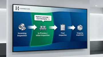
The four types of inspection
Understanding where inline fits within the broader quality framework helps clarify its advantage. Quality inspection is categorised into four stages:
- Incoming inspection — raw material verification
- In-process (inline) inspection — during production
- Final inspection — finished goods assessment
- Outgoing inspection — pre-shipment verification
Inline inspection offers the highest leverage of the four. Catching a defect before coating, laminating, or finishing avoids layering cost onto material that will ultimately be scrapped—a compounding loss that grows with every stage a non-conforming product advances through.
Core Techniques Used in Inline Surface Inspection
Optical and camera-based inspection
Line scan cameras capture one row of pixels at a time, building continuous high-resolution images of moving surfaces. Modern systems achieve extreme resolution—up to 32,768 pixels at 400 kHz line rates with pixel sizes down to 2.5 µm—enabling detection of microscopic scratches, pinholes, color inconsistencies, and foreign particles at full production speed.
Structured lighting enhances contrast for subtle defects:
- Diffused dome lights for reflective or rough surfaces
- LED line illuminators providing powerful, homogeneous beams matched to line scan geometry
- Off-axis lighting to eliminate glare on specular surfaces
Optical systems excel at detecting visible surface anomalies on rigid or flat materials like metal sheets, plastics, and wood panels.
Laser profilometry and 3D surface measurement
Laser triangulation systems project laser lines onto surfaces and calculate height differences based on reflected profiles, reconstructing detailed 3D surface maps. Leading systems achieve z-axis repeatability down to 0.03 µm with scan rates up to 64 kHz, enabling detection of flatness deviations, warpage, and micro-level roughness variations.
Applications include:
- Flatness measurement by calculating height differences from a best-fit plane
- Warpage detection on PCBs, material edges, and chassis
- Surface texture analysis according to ISO 25178 standards
Unlike optical cameras, laser profilometry captures true geometric data — making it the go-to method when height variation matters as much as surface appearance.
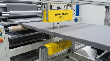
Non-contact electromagnetic and millimeter-wave sensing
Millimeter-wave (MMW) technology uses electromagnetic waves to measure thickness and detect surface-level inconsistencies without physical contact. Frequency-modulated continuous-wave (FMCW) sensors operating in the 30–300 GHz range offer high penetration depth for thick materials and measurement rates of several kilohertz. For delicate substrates, that non-contact capability is critical.
The compression problem with contact-based sensing:
Contact sensors physically compress soft materials like nonwovens and foam, distorting thickness readings and risking surface damage. MMW sensors operate at a safe standoff distance, eliminating compression bias entirely. Hammer-IMS's M-Ray technology takes this further — delivering non-nuclear, contactless thickness measurement for nonwovens, foam, technical textiles, and plastics where even light contact would compromise measurement accuracy or damage the product.
Advantage over nuclear gauges:
Nuclear gauges require specific materials licenses, radiation safety training, and strict regulatory compliance. MMW technology is non-nuclear and emits no harmful radiation — eliminating licensing burdens, disposal requirements, and ongoing safety management costs entirely.
Real-time software analysis and pass/fail thresholding
Once sensing data arrives, software does the heavy lifting. Inspection software receives data continuously, calculates surface parameters (roughness values, thickness, defect dimensions), and compares them against quality thresholds. When deviations occur, the system triggers visual/audible alerts or automatic rejection mechanisms.
Advanced capabilities include:
- Surface maps and roughness distribution displays that help operators locate defects immediately
- AI-driven defect classification with 92–98% accuracy
- Hybrid algorithms combining density-based clustering, curvature analysis, and boundary estimation
Data logging and connectivity
Contemporary inline systems integrate with factory networks using industrial protocols like PROFINET, OPC UA, and EtherCAT. This connectivity enables:
- Historical inspection data capture for root-cause analysis
- Trend analysis and statistical process control (SPC) reporting
- Integration with MES and ERP systems for enterprise-wide quality visibility
Key Benefits of Inline Surface Inspection
Immediate defect detection and containment
Inline inspection catches defects the moment they form — before non-conforming material has traveled metres further down the line. The faster a process deviation is identified, the shorter the run of out-of-spec product that needs to be scrapped or reworked.
Documented impact:
| Industry | Scrap/Defect Reduction | Financial Impact |
|---|---|---|
| Aerospace Precision Parts | 35% reduction (4.8% to 3.1%) | 805K annual savings |
| Automotive Stamping | 75% reduction (12% to 3%) | 2.8 million annual savings (8-month ROI) |
| Electronics Assembly | 90% reduction in placement errors | 1.2 million annual savings |
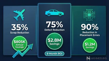
Setting quality gates early in the process enables manufacturers to reduce scrap by 70–85% compared to catching defects at final inspection.
Reduced material waste and production scrap
Real-time detection enables operators or automated systems to intervene quickly, minimizing the volume of off-spec material that continues to be processed. This directly supports sustainability goals: every tonne of steel scrap used avoids 1.5 tonnes of CO₂ emissions and conserves 1.4 tonnes of iron ore.
Hammer-IMS's M-Ray systems reduce material waste by enabling tighter thickness margins and uniform coverage, preventing the over-application of coatings or materials that would otherwise be trimmed and scrapped.
Closed-loop process control
Closed-loop systems connect inspection data directly to process actuators—die lip adjusters, coating heads, calender gaps—to automatically correct process drift before it produces out-of-spec product.
Real-world examples:
| Application | Correction Mechanism | Outcome |
|---|---|---|
| Hot Strip Mill | Adjusts roll gap, speed, cooling based on thickness/flatness data | 90%+ of non-conformances corrected within the same coil |
| Powder Coating | Adjusts powder quantity based on pre-cure measurements | Eliminates safety margins, reducing powder consumption |
| Strip Surface Quality | Cameras detect scale; feedback adjusts descaling spray pressure | 40–55% reduction in customer claims within 6 months |
These loops operate in milliseconds to seconds — fast enough that the process corrects itself before the deviation compounds into a larger quality event.
100% coverage vs. sampling
Closed-loop correction only works if every defect is seen. That's where continuous coverage matters: inline inspection examines every unit or metre of material, eliminating the statistical risk of defects slipping through between sample intervals. Performing 100% inspection is the only way to assure no defective items leave the factory—critical in industries with zero-defect requirements like medical devices, automotive safety components, and aerospace.
Reduced labour costs and operator dependency
Automated inline inspection replaces manual visual checks that are inconsistent, fatigue-dependent, and unable to maintain pace with modern production speeds. Quality personnel shift from repetitive pass/fail decisions to higher-value work — root-cause analysis, process optimisation, and data-driven improvement projects that actually reduce defect rates over time.
Choosing the Right Inline Inspection Technique for Your Application
Material and product type
Optical/camera systems excel for visible surface defects on rigid or flat materials—metal sheets, plastics, wood panels—where lighting can be controlled.
Laser profilometry is required for detailed 3D profiles, long-range accuracy, and dynamic environments where precise geometry matters.
Non-contact electromagnetic or millimeter-wave systems suit soft, porous, or translucent materials: nonwovens, foam, textile webs. Where optical access is limited or physical contact would damage the product, millimeter-wave-based systems like M-Ray measure without touching the material at all.
Production speed and line integration
Line speed, web width, available mounting space, and required integration with existing PLC/SCADA systems all affect system selection. Buyers should evaluate:
- Sensor scan rates and data throughput (kHz line rates for high-speed lines)
- Connectivity options: PROFINET, EtherCAT, OPC UA, Modbus TCP/IP
- Compatibility with existing factory network architecture
Once integration constraints are mapped, the next filter is sensing principle—which depends entirely on the defect type you need to catch.
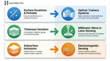
Sensitivity requirements and defect type
Different defect types require different sensing principles:
- Surface scratches and pinholes → Optical/camera systems
- Thickness variation → Millimeter-wave or laser
- Subsurface inclusions → Electromagnetic sensing
Before selecting any technology, define your critical defect specifications:
- Minimum detectable defect size
- Required measurement resolution
- Acceptable false-positive rate
Frequently Asked Questions
What is an inline inspection?
Inline inspection is a quality control process where measurement or detection systems are integrated directly into the production line, continuously evaluating products or materials as they move through manufacturing. This enables real-time defect detection without stopping or slowing production.
What is the difference between inline and final inspection?
Inline inspection monitors quality during production so defects are caught immediately and further processing of non-conforming material is prevented. Final inspection examines finished products after all manufacturing steps are complete, meaning defects found have already consumed additional processing resources.
What are the 4 types of inspection?
The four standard types are incoming inspection (raw materials), in-process or inline inspection (during production), final inspection (finished goods), and outgoing inspection (pre-shipment).
What types of surface defects can inline inspection detect?
Common detectable defects include scratches, pinholes, inclusions, coating inconsistencies, thickness variations, roughness deviations, edge defects, and pattern irregularities. The specific defect types a system can catch depend on the sensing technology used: optical for visible anomalies, laser for 3D geometry, and electromagnetic for thickness.
Is inline surface inspection suitable for all materials and industries?
Inline inspection is adaptable to a wide range of materials and industries through different sensing technologies. Optical systems suit rigid surfaces, while millimeter-wave or laser systems handle soft, transparent, or compressible materials, making it applicable across textiles, plastics, metals, and paper.
How does inline surface inspection contribute to waste reduction?
By detecting out-of-spec conditions immediately, inline systems allow operators to correct process deviations before large quantities of defective material are produced. The result is lower scrap rates, reduced rework volume, and less raw material consumption across the production run.