Introduction
By the time a surface defect reaches final inspection in continuous manufacturing, the cost to fix it has already compounded. The American Society for Quality (ASQ) 1-10-100 rule quantifies this clearly: if detecting and fixing a defect in-line costs €1, catching it during production jumps to €10, and post-production fixes escalate to €100.
For manufacturers of continuous materials — plastic films, nonwovens, textiles, and foams — that cost multiplier compounds further because defects propagate across metres of material before anyone spots them.
That's why the inspection method you choose matters far beyond technical specification. It shapes throughput capacity, production yield, regulatory compliance, and whether your quality control catches defects after the fact or prevents them through real-time process feedback. This guide explains the core surface inspection methods, walks through a practical implementation process, and shows how to match the right approach to your material type and application.
Key Takeaways
- Surface inspection detects defects, irregularities, and dimensional deviations on materials during or after production
- Methods include manual visual checks, machine vision, laser scanning, tactile probes, and advanced millimeter wave systems
- Choosing the right method depends on material properties, defect sensitivity, production speed, and whether contact is acceptable
- Automated real-time systems deliver the highest accuracy and support closed-loop production control
- Continuous web materials — films, foams, fabrics, nonwovens — benefit most from contactless, non-nuclear measurement
What Is Surface Inspection and Why Does It Matter?
Surface inspection evaluates a material or component's outer layer for defects — scratches, cracks, voids, thickness deviations, contamination — as part of structured quality control. It applies to both discrete manufactured parts and continuous web materials moving through production lines at high speed.
Surface defects fall into two categories: functional defects that compromise structural integrity, conductivity, or sealing performance, and aesthetic defects that damage consumer perception and brand standards. The downstream impact varies by industry:
- A void in an insulation foam panel reduces thermal performance
- A thickness deviation in plastic film causes sealing failures in packaging
- A surface crack in steel sheet can trigger catastrophic failure in automotive components
These consequences make the timing of detection critical. Surface inspection plays a dual role: it catches defects and generates data that feeds back into manufacturing adjustments in real time.
Early-stage detection is far cheaper than end-of-line remediation. Research confirms that fixing defects in production costs 10–100 times more than catching them during development — with cost multipliers reaching 1,500× when problems surface at the operations phase.

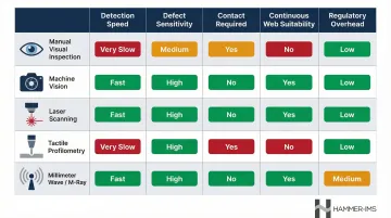
Key Surface Inspection Methods
No single inspection method works for every material or application. Manufacturers typically combine two or more approaches based on their specific defect profile, material characteristics, and production constraints. This section provides a practical guide to understanding each method's strengths, limitations, and best-fit use cases.
Manual Visual Inspection
Manual inspection remains the baseline method: a trained operator visually examines surfaces under controlled lighting conditions. It offers low initial cost and flexibility to adapt to varying defect types without reprogramming.
Human factors research reveals a critical weakness, however. When defects are rare (1–2% prevalence), manual inspectors suffer miss rates up to 30% due to psychological criterion shifts. In textile manufacturing, inspector fatigue during extended periods pushes missed inspection rates to 15–30%. Manual inspection cannot match high-speed production lines or detect sub-millimetre defects reliably.
Best for: Low-volume production, varied product types, initial quality assessments, secondary verification.
Optical Camera-Based (Machine Vision) Inspection
Machine vision systems combine high-resolution cameras with structured lighting (brightfield, darkfield, UV) to capture surface images. Software analyses these images against reference parameters to flag anomalies in real time.
Time Delay Integration (TDI) line-scan cameras reach line rates up to 100 kHz with 10.56 µm pixel sizes, enabling 100% surface coverage without motion blur on fast-moving webs. Key advantages include consistent inspection speed, repeatability, and integration with automated reject systems.
Critical success factor: Lighting optimization. Darkfield defects require nearly 8 times more light than brightfield defects, and incorrect lighting geometry eliminates the contrast needed for reliable detection.
Best for: High-speed continuous webs, cosmetic defect detection, applications requiring 100% inspection coverage.
Laser Scanning
Laser scanning projects a focused beam across the surface while photodetectors capture reflected or scattered light, generating precise surface topography data. This method excels at detecting pits, protrusions, roughness variations, and particles on both smooth and semi-textured surfaces.
The technology delivers high spatial sensitivity where optical cameras struggle — but calibration demands are significant. Ambient lighting interference and vibration sensitivity limit deployment to more controlled production environments.
Best for: 3D surface profiling, roughness measurement, detecting small protrusions or depressions.
Tactile / Contact Profilometry
Contact profilometers use diamond-tipped stylus probes to physically trace surface profiles, measuring roughness with sub-nanometre vertical resolution. High-precision systems offer 0.4 nm resolution on finest ranges.
The trade-off is speed and applicability. Stylus profilometers operate at a few hundred micrometres to a few millimetres per second, making them impractical for high-speed production. Physical contact risks surface damage on soft materials (plastics, coatings, nonwovens) and introduces measurement variability. Vibration sensitivity restricts use to controlled metrology labs rather than production floors.
Best for: Offline calibration, reference standard verification, laboratory analysis of rigid materials.
Advanced Non-Contact Methods: Millimeter Wave and M-Ray Technology
Millimeter wave and terahertz (THz) technologies provide non-destructive, contact-free measurement of continuous materials. These systems scan in real time, measuring thickness uniformity, density variations, and surface/subsurface irregularities without touching the product.
THz Time-Domain Spectroscopy and Frequency-Modulated Continuous-Wave (FMCW) systems can measure multi-layer thicknesses down to approximately 5–6 µm, with measurement rates reaching several kilohertz. The technology penetrates optically opaque polymers, foams, and paper, making it effective where optical systems fail.
Hammer-IMS's M-Ray technology employs electromagnetic millimeter waves at 60 GHz for basis-weight and thickness measurement. Key advantages over nuclear alternatives include:
- No regulatory licensing — eliminates permit requirements common with beta or X-ray gauges
- Consistent measurement precision regardless of material colour, transparency, or thickness variation
- Non-nuclear and non-radioactive, removing radiation safety compliance overhead
Best for: Continuous web materials (textiles, nonwovens, plastic films, foams), applications requiring non-contact measurement, environments with strict safety and environmental compliance.
AI-Integrated Automated Inspection
Modern surface inspection increasingly layers machine learning over optical or sensor data to identify complex patterns that rule-based systems miss. Deep learning algorithms learn autonomously from training data, handling diverse and intricate defect types without manual parameter tuning.
Research demonstrates that YOLOv11-based systems for textile defect detection achieve mean Average Precision exceeding 82% across multiple synchronized video sources in real-time industrial settings. The global AI inspection market is projected to grow from $33.07 billion in 2025 to $102.42 billion by 2032, reflecting accelerating adoption in high-volume and safety-critical manufacturing.
Best for: Complex defect patterns, adaptive quality thresholds, predictive defect detection, applications requiring continuous learning.
How to Implement a Surface Inspection Process: Step by Step
The most common failure points in surface inspection implementation are vague defect definitions at the start and no feedback loop at the end. This roadmap addresses both.
Step 1 – Define the Inspection Objective
Specify exactly what defect types need detection (dimensional, cosmetic, structural), establish clear pass/fail thresholds, and identify which production stage will host the inspection system.
Ambiguous objectives create two costly problems: over-rejection (false positives) that waste good material, and missed defects (false negatives) that reach customers.
For example, defining "surface void" without specifying minimum detectable size, acceptable frequency per square metre, or critical versus cosmetic classification leads to inconsistent quality decisions.
Action: Document specific defect types, size thresholds, acceptable defect density, and inspection stage location.
Step 2 – Characterise the Material and Defect Profile
Analyse your material's physical properties: surface texture, opacity, reflectivity, thickness range, and production speed. Map the defect types most likely to occur based on process history and failure mode analysis.
Material characteristics directly constrain which inspection methods are viable. A transparent film requires different lighting than an opaque nonwoven. A delicate foam cannot tolerate contact measurement. A web moving at 500 metres per minute eliminates slow scanning methods.
Action: Create a material specification sheet and historical defect frequency chart to guide method selection.
Step 3 – Select and Configure the Right Method
Match your defect profile and material characteristics to the appropriate inspection method using the criteria outlined above. Remember that sensor choice is only part of the equation — lighting setup, sensor positioning, and calibration are equally critical.
Testing in a lab or pilot environment before full production deployment avoids costly rework. Many suppliers offer application validation services to confirm system performance on your specific material.
Action: Conduct pilot testing with known defect samples to validate detection accuracy, false positive rates, and integration compatibility.
Step 4 – Integrate with the Production Line
Effective integration requires mechanical mounting, software connectivity, and data exchange protocols. The inspection system must connect to line PLCs or process control systems, establishing real-time data logging and enabling automated responses.
Closed-loop integration — where inspection data automatically triggers production parameter adjustments — delivers measurable efficiency gains by correcting deviations before scrap accumulates. Thickness measurement data fed to extrusion die controls is a typical example of this in practice.
Action: Establish industrial communication protocols and configure automated adjustment triggers. Common options include:
- OPC UA
- Ethernet/IP
- PROFINET
Step 5 – Review, Validate, and Continuously Improve
Validate system performance against known defect samples at installation and track false positive/negative rates over time. Production conditions change — raw material variations, equipment wear, process modifications — and inspection thresholds must adapt accordingly.
Regular review of detection performance, root cause analysis of escaped defects, and threshold refinement keep the system effective over time.
Action: Implement monthly performance reviews, tracking detection accuracy, false alarm rates, and process improvement actions triggered by inspection data.
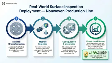
Surface Inspection in Practice: A Real-World Walkthrough
The following scenario shows how these method-selection principles play out on an actual production line. A nonwoven fabric manufacturer producing automotive insulation material at 300 metres per minute faces two primary defect types: thickness variation exceeding ±10% tolerance and surface voids larger than 2 mm diameter.
Here is how the decision and deployment unfold across four steps:
Material characterisation — The nonwoven is opaque, textured, and exits the bonding stage at around 100°C. Production speed and surface temperature immediately rule out contact measurement.
Method selection — The team evaluates machine vision (effective for surface voids) and millimeter wave measurement (effective for thickness uniformity). They choose both: camera-based inspection for void detection and M-Ray technology for thickness, running as non-contact systems in parallel.
Configuration and integration — Both systems are positioned directly after the bonding stage to measure hot material in real time. Thresholds are set as follows:
- Voids >2 mm trigger line marking for downstream trim
- Thickness deviations >8% trigger automatic process alerts
- Deviations >12% initiate automatic line speed reduction
Closed-loop outcome — After three months, data logs reveal a recurring thickness deviation pattern tied to a specific shift and machine temperature setting. Automatic adjustments cut scrap rate by 18%. Root cause analysis then eliminates the underlying variation entirely — a result that offline sampling would have taken months longer to surface.
How Hammer-IMS Can Help
Hammer-IMS specialises in non-contact, non-nuclear quality and process control measurement for industries producing continuous materials — textiles, nonwovens, plastic films, foams, and composites — where standard optical or tactile systems fall short in speed, safety, or material compatibility.
M-Ray technology enables contactless, real-time surface and thickness measurement using electromagnetic millimetre waves at 60 GHz. Unlike nuclear-based gauges, M-Ray systems require no radiation emission licences in most cases, removing a significant layer of regulatory overhead whilst delivering precise basis-weight and thickness data.
The technology works regardless of material colour, transparency, or thickness — including hot, freshly extruded materials measured directly on the line.
Connectivity 3.0 software ties M-Ray measurement data directly into production control systems. Key capabilities include:
- Closed-loop feedback that automatically adjusts process parameters when deviations are detected
- Reduced production margins and minimised material waste
- Data logging and analytics integration with existing manufacturing systems
- No radioactive measurement sources required at any point
Manufacturers including Owens Corning, Balta, and Autoneum have deployed M-Ray systems across nonwoven, textile, and insulation production environments.
To discuss your specific inspection challenge and explore how M-Ray technology can be configured for your material type and production environment, contact Hammer-IMS at +32 11 36 55 01 or visit www.hammer-ims.com.
Frequently Asked Questions
What is the difference between contact and non-contact surface inspection methods?
Contact methods like tactile profilometers physically touch the surface using diamond-tipped probes, offering high precision for small areas but risking damage to delicate or fast-moving materials. Non-contact methods (optical, laser, millimeter wave) inspect without touching, making them suitable for continuous production lines, high-speed webs, and sensitive materials where contact would introduce deformation or measurement variability.
Which surface inspection method works best for continuous web materials like films and textiles?
Non-contact methods are best suited for continuous web materials due to production speed and material sensitivity. Millimeter wave-based systems, for example, measure thickness and surface uniformity across the full web width in real time, enabling 100% inspection coverage at line speeds whilst avoiding damage to the material.
How does automated surface inspection improve quality control over manual inspection?
Automated systems run at production line speeds with consistent, fatigue-free detection — catching defects human inspectors would miss. They also generate Statistical Process Control data, turning inspection into an active tool for closed-loop process improvement rather than a passive defect catch.
Can surface inspection systems be integrated with production line controls?
Modern systems connect to PLCs and production software via protocols such as OPC UA, PROFINET, and Ethernet/IP. A detected deviation can automatically trigger a corrective parameter change (for example, die bolt adjustment in extrusion), reducing waste and preventing defect propagation without operator intervention.
What types of defects can surface inspection detect?
Common detectable defects include scratches, cracks, voids, pits, contamination particles, thickness deviations, surface roughness variations, and pattern irregularities. The specific detectable defect types depend on the inspection method and sensitivity configuration used — optical systems excel at cosmetic surface defects, laser scanning detects topography variations, and millimeter wave systems measure thickness uniformity and density variations.
How do you choose the right surface inspection method for your application?
Start by evaluating these four factors:
- Material properties: opacity, texture, and line speed
- Defect requirements: the type and minimum size you need to detect
- Throughput: whether the method can keep pace with production
- Contact tolerance: whether touching the material is acceptable
For continuous web applications, prioritise non-contact methods. Validate your chosen approach with pilot testing before full deployment.