
Introduction
A geosynthetic failure in the field doesn't just mean a failed product — it means contaminated groundwater, destabilized embankments, and remediation bills that dwarf the original construction cost. Poor surface quality is one of the most common and preventable causes. Research shows that improper design or installation can escalate remediation costs exponentially: prevention runs around $15,000; repair can reach $1.3 million — an 87x multiplier.
These polymeric products — geotextiles, geomembranes, geogrids, geosynthetic clay liners (GCLs) — serve civil, environmental, and geotechnical infrastructure in roles ranging from soil reinforcement to drainage, filtration, and containment. Each type carries different surface quality requirements.
That diversity makes robust inspection both demanding and consequential. This post covers why surface inspection matters, which methods are used, a step-by-step inspection process, and how modern measurement technologies are helping manufacturers and engineers close the quality loop.
Key Takeaways
- Geosynthetics surface inspection spans visual, mechanical, permeability, and chemical methods — applied at both manufacturing and field deployment stages
- Thickness uniformity, tensile integrity, and surface defects directly determine how well a geosynthetic performs in service
- International standards (ASTM, AASHTO, ISO) govern inspection, using both index and performance/design tests
- Defects missed during manufacturing are far harder and costlier to fix once material is installed in the field
- Automated non-contact measurement catches surface and thickness deviations during production, before defective material ships
Why Surface Inspection Is Critical in Geosynthetics Manufacturing and Application
Surface quality directly determines functional performance. A geotextile with inconsistent thickness or mass-per-unit-area will have unpredictable filtration and drainage behavior. A geomembrane with surface micro-voids or thin spots will fail as a fluid barrier under stress. When a landfill cell experienced complete barrier failure due to a punctured liner, remediation required excavating and relining the entire 4-acre cell.
The cost and safety consequences of inspection failures are severe. Undetected surface defects that reach installation can lead to embankment failures, contaminated groundwater, costly rework, and litigation. Industry estimates suggest defect prevention costs a fraction of post-failure remediation. In January 2026, a landfill operator agreed to a $1.9 million penalty for violations including holes in primary and overlay liners that caused leachate leaks.
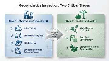
Managing this risk means catching defects at two distinct stages before they become field failures:
- Manufacturing/production-stage QC — Inline or laboratory testing catches deviations before rolls leave the factory
- Field installation QC — Visual checks and sampling confirm delivered material meets specification and has survived handling without damage
Key Surface Inspection Methods for Geosynthetics
Visual Inspection
Visual inspection is the first and most universal method. Inspectors examine the surface for breaks, tears, holes, thin spots, contamination, weaving defects (in woven geotextiles), or welding anomalies (in geomembranes). It is fast and non-destructive but highly dependent on inspector experience and lighting conditions.
For critical applications, visual inspection alone isn't enough. Electrical leak detection (ELD) detects pinholes as small as 1 mm—defects the human eye routinely misses under field conditions.
Physical and Mechanical Property Testing
Physical property tests evaluate structural integrity of the geosynthetic surface and bulk material. Key tests include:
- Tensile strength (grab and wide-width)
- Tear strength
- Puncture resistance
- Mass per unit area (weight)
Tests are conducted per ASTM D4759, ASTM D4632, and ISO 10319:2024 standards. Results are compared against Minimum Average Roll Values (MARVs)—the industry benchmark for specification compliance.
MARVs are calculated as the mean value minus two standard deviations across a defined lot. This approach delivers a 97.7% confidence level that any sampled roll will meet or exceed the declared specification value.
Thickness and Dimensional Measurement
Thickness is a foundational surface property—it affects tensile performance, hydraulic behavior, and durability. Conventional measurement uses calipers and thickness gauges applied at specific points on the roll.
Limitations of spot measurement:
- Contact pressure compresses nonwovens, causing measurement errors
- Point measurements miss cross-machine variations
- Sampling only from roll ends fails to capture full-width consistency
For production environments, contactless and non-destructive scanning technologies allow continuous cross-web thickness profiling during manufacturing—far more capable than periodic spot checks.
GRI GM13 standards for HDPE geomembranes specify:
- Testing required on every roll
- 10 specimens taken across the full roll width
- Average must equal nominal thickness; individual minimums cannot fall below -10% (smooth) or -15% (textured) of nominal
Hydraulic and Permeability Testing
Water permeability is critical for geotextiles used in filtration and drainage roles. Permeability tests measure the rate and resistance of water flow through the fabric to confirm it will neither clog too quickly nor allow excessive soil particle migration.
Two primary hydraulic properties:
- Permittivity (ψ, s⁻¹): Measures cross-plane water flow rate per unit area per unit head—critical for filtration applications where water passes through the fabric while retaining soil
- Transmissivity (θ, m²/s): Measures flow rate per unit width parallel to the geosynthetic plane—critical for drainage applications where fluids transport along the material
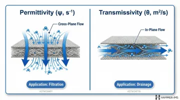
These tests validate the adequacy of the fabric's surface pore structure for its intended application. Tests follow ASTM D4491 for permittivity and ASTM D4716 for transmissivity.
Chemical Resistance and Environmental Adaptability Testing
Geosynthetics in landfill lining, mining, or agricultural containment must resist chemical attack from leachates, acids, or hydrocarbons. Immersion and chemical penetration tests replicate long-term exposure conditions, while environmental adaptability tests (UV weathering, thermal cycling, freeze-thaw) simulate in-service stresses.
Because no universal numeric lifespan applies to geomembranes in aggressive environments, durability is determined through site-specific chemical compatibility testing (ASTM D5322) and accelerated aging protocols (ASTM D5721).
How a Geosynthetics Surface Inspection Process Works — Step by Step
In practice, surface inspection of geosynthetics follows a structured process combining pre-production specification setting, in-process measurement, and post-production validation, with clear decision points at each stage. Skipping or compressing any step is a common cause of non-conforming material reaching the field.
Step 1 – Define Scope and Inspection Criteria
Clarify the material type, intended application (e.g., road base reinforcement vs. landfill liner), and the governing specification or standard:
- ASTM D5261 for mass per unit area
- ASTM D4759 for tensile
- AASHTO M288 for highway geotextiles
Establish the inspection attributes to test and their pass/fail thresholds. Align inspection criteria with Minimum Average Roll Values to ensure statistical confidence.
Step 2 – Prepare and Sample the Material
Develop a sampling plan with a documented frequency. ASTM D4354 is the standard sampling protocol for geosynthetics, providing specific tables dictating the number of units to select based on whether the sampling is for Manufacturer's Quality Control (MQC), Quality Assurance (MQA), or Purchaser's Specification Conformance.
Critical sampling rules:
- Use random, not selective, sampling
- Define lots and sublots clearly
- Label and identify samples properly
- Sample across the full roll width, excluding inner/outer wraps and folds
Sampling only from roll ends fails to capture cross-machine variability and manufacturing defects that occur in the center of the web.
Step 3 – Conduct Surface and Visual Inspection
Examine roll surfaces under adequate lighting for tears, pinholes, thin bands, contamination, and bonding failures. For geomembranes, electrical leak testing (ELD) per ASTM D6747 supplements visual inspection for pinholes or weld defects.
Even with strict Construction Quality Assurance (CQA), exposed geomembranes average 4 leaks per hectare, rising to 22 leaks per hectare without CQA. Record all findings on standardized inspection report forms and flag any sublots for follow-up testing.
Step 4 – Perform Instrumental Testing
Flagged specimens and random-sample units move to instrumental testing. Execute the applicable mechanical and physical tests:
- Thickness
- Tensile strength
- Permeability
- Chemical resistance
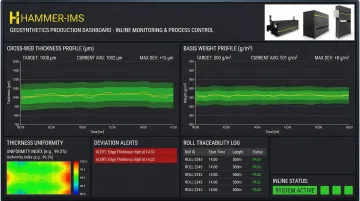
For production environments, inline non-contact measurement systems (based on millimeter-wave or capacitive technologies) allow continuous monitoring of thickness and weight across the full web width, replacing periodic spot checks with real-time data.
That shift from spot checks to continuous profiling has measurable impact. In one documented case, a manufacturer using continuous profiling reduced scrap/rejection rates from 10–15% to 0.5%, saving over $200,000 in disputed material costs.

Step 5 – Interpret, Document, and Act on Results
Evaluate results against specification thresholds:
- Individual out-of-tolerance readings
- Statistical process control signals
- Isolated defects vs. systemic production issues
Action protocol:
- Accept lot if all tests pass
- Quarantine for re-test if borderline readings exist
- Reject lot if critical failures occur
- Initiate corrective action if systemic process deviations appear
Retain all inspection data in a QC record system for traceability, regulatory audits, and continuous improvement.
How Hammer-IMS Can Help with Geosynthetics Quality Control
Hammer-IMS is a specialist provider of non-nuclear, contactless measurement systems for industrial production lines—with direct applicability to geosynthetics and nonwoven manufacturers looking to move beyond manual spot-check inspection toward continuous inline quality control.
M-Ray technology uses advanced millimeter-wave sensors to measure thickness and basis weight across the full web width, without contact, radiation, or production interruption. This technology enables manufacturers to detect surface variations as they form—not after a roll is completed.
Operational benefits for geosynthetics producers:
- Catches surface variations during production with real-time cross-web thickness profiles
- Connects measurement data directly to process adjustments—calender gap, process temperature, and more
- Logs full traceability data for every roll produced
- Eliminates material waste by replacing destructive sampling with non-destructive testing
These capabilities directly address the most common source of surface non-conformance—gradual drift in calender gap or process temperature that creates thin zones invisible to visual inspection.
Unlike nuclear gauge systems, M-Ray technology requires no radiation licensing, no shielding infrastructure, and no disposal protocols—removing significant compliance overhead for manufacturers. Hammer-IMS supports geosynthetics producers across Europe, Australia, and Japan, with implementation backed by local partners including ADSTEC.
Conclusion
Effective geosynthetics surface inspection combines visual, mechanical, hydraulic, and chemical methods across both manufacturing and installation stages. Governed by recognized standards and backed by calibrated measurement systems, the quality of that inspection determines whether a geosynthetic delivers its intended design life in the field.
As geosynthetics move into more demanding environments—deeper landfills, softer foundation soils, more aggressive chemistries—inspection must shift from reactive sampling to continuous, inline monitoring. Systems like Hammer-IMS's non-contact M-Ray technology represent this shift: measuring thickness and basis weight in real time during extrusion, so deviations are caught before defective rolls leave the production line rather than discovered during field testing.
Frequently Asked Questions
What are geosynthetics used for?
Geosynthetics serve six primary functions: reinforcement, separation, filtration, drainage, erosion control, and fluid containment. In practice, this covers everything from road base stabilization and retaining wall support to landfill lining and pond barriers.
Which geosynthetic property is critical for determining its effectiveness in reinforcement?
Tensile stiffness and strength—measured as tensile modulus and ultimate tensile strength—are the primary properties for reinforcement applications. The geosynthetic's ability to mobilize resistance at low strain is critical for effective soil interaction and load transfer in reinforcement functions.
What is the IRC code for geosynthetics?
IRC:SP:59-2019 "Guidelines for Use of Geosynthetics in Road Pavements and Associated Works" governs geosynthetics in road construction in India. Internationally, ASTM, AASHTO, and ISO standards are the most widely referenced frameworks for geosynthetics specification and testing.
What are the main methods used to inspect geosynthetic quality?
Five primary inspection methods are used:
- Visual/surface inspection — tears, holes, contamination
- Physical and mechanical testing — tensile, tear, puncture strength
- Thickness and dimensional measurement
- Hydraulic permeability testing — permittivity and transmissivity
- Chemical resistance testing — immersion and UV weathering
Why is thickness uniformity important in geosynthetics surface inspection?
Thickness uniformity governs mechanical performance, hydraulic behavior, and barrier integrity. Thin zones from production inconsistencies concentrate stress and fail first under load or chemical exposure — directly compromising long-term field reliability.
What is the difference between index tests and design tests for geosynthetics?
Index tests (most standard ASTM tests) measure properties under standardized conditions, enabling product comparison and quality control. Design tests simulate actual field boundary conditions, producing values engineers can plug directly into structural calculations. A single test can serve both roles depending on how results are applied.