Introduction
Measuring dry film thickness (DFT) on concrete is a quality control checkpoint that directly affects structural longevity and maintenance costs. Apply a coating too thin, and moisture penetration accelerates—triggering carbonation, chemical attack, and rebar corrosion that contributes to the water and wastewater sector's $36 billion annual corrosion burden and the $18 to $21 billion spent annually on U.S. concrete repair.
Over-application brings its own failures: solvent entrapment, internal stress cracking, delamination, and material waste that turns a protective coating into a liability.
Concrete presents distinct measurement challenges compared to metal substrates. Its non-conductive, porous, and variable surface profile renders magnetic induction and eddy current gauges—standard tools for metal—completely ineffective. This guide covers the right tools for concrete substrates, how to apply ultrasonic and destructive testing methods correctly, how to read results against accepted industry criteria, and which common errors undermine measurement reliability.
Key Takeaways
- Ultrasonic gauges are the primary non-destructive method for concrete; magnetic/eddy current tools used on metal will not work
- Always apply couplant (gel or water) and ensure flat probe contact
- Average multiple readings, since single measurements are unreliable on porous concrete surfaces
- Calibrate before each session using reference standards per ASTM D6132 or ISO 2808
- Act on out-of-spec results immediately: thin readings require recoating, thick readings require adhesion investigation
What You Need to Measure Dry Film Thickness on Concrete
Tool selection depends on coating type, thickness range, whether destructive testing is acceptable, and whether you're working in field inspection or production-line quality control. For most concrete coating work, the following equipment covers the essentials.
Tools and Materials Required
Essential equipment includes:
- Ultrasonic DFT gauge rated for concrete (primary NDT tool)
- Couplant (propylene glycol gel or water)
- Calibration shims or reference standards traceable to ASTM/ISO
- Cleaning cloths or lint-free tissue
- Data recording method (logbook or digital logger)
Advanced gauges include coating material libraries that eliminate manual entry of acoustic properties for common coatings such as epoxy, latex, polyurethane, or polyurea. The DeFelsko PosiTector 200 and Elcometer 500 feature onboard libraries that cut setup time in the field.
Preconditions and Setup
Before measurement:
- Confirm full cure — partially cured coatings produce inaccurate readings and can be damaged by probe contact
- Remove loose debris, standing water, and surface contaminants that disrupt acoustic coupling
- Zero the gauge on bare substrate to account for surface profile variation
Methods to Measure Dry Film Thickness on Concrete
Because concrete is non-metallic, magnetic induction and eddy current methods do not apply. Three practical methods exist: ultrasonic testing (NDT), dedicated concrete coating gauges, and destructive cross-section testing. Method choice depends on accuracy requirements, acceptable coating damage, and measurement range.
Method 1: Ultrasonic Testing (Non-Destructive)
Description: Ultrasonic testing sends a high-frequency sound pulse.pdf) through the coating; the pulse reflects off the coating-substrate interface, and the gauge calculates thickness from the time of flight and speed of sound in the coating material.
Tools Needed:
- Ultrasonic DFT gauge with concrete-rated probe (e.g., 50–3,800 µm range)
- Couplant gel (propylene glycol-based) or water
- Calibration standards
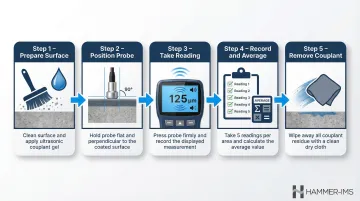
Step-by-Step:
- Prepare the surface — Clean the measurement area and apply a small drop of couplant gel (or water on smooth horizontal surfaces)
- Position the probe — Place the probe flat and perpendicular on the surface; do not tilt or drag
- Take reading — Press gently until the gauge signals completion (audible beep or green indicator); lift the probe cleanly between readings
- Record and average — Take minimum 5 readings per area per ASTM D6132, discard statistical outliers from pores, calculate average
- Remove couplant — Wipe surface with water to prevent contamination
- Pro: Best non-destructive, field-ready option across a wide coating range (8 µm to 7.60 mm)
- Con: Rough or highly porous concrete can cause reading variation and may require additional measurements
Method 2: Dedicated Concrete Coating Thickness Gauge
Description: Specialised ultrasonic gauges designed exclusively for concrete and masonry eliminate manual configuration of measurement gates or acoustic velocity. Users select coating type from an onboard library and the gauge handles calibration automatically.
Tools Needed:
- Dedicated concrete coating gauge with replaceable probe tip
- Couplant (check manufacturer guidance — many still require gel or water)
Step-by-Step:
- Select coating material — Power on gauge, choose coating type from library (epoxy, latex, etc.)
- Verify signal — Confirm green signal strength indicator before accepting any reading
- Measure systematically — Place probe flat without excess force; take readings in a grid pattern
- Use scan mode — Available on models like the Elcometer 500 (140+ readings/minute) for high-density coverage of large surfaces
Comparison of Leading Dedicated Gauges:
| Feature | Elcometer 500 | DeFelsko PosiTector 200 |
|---|---|---|
| Range on Concrete | C1: 150-2,500 µm C2: 750-9,000 µm |
C1: 50-3,800 µm D1: 50-7,600 µm |
| Scan Mode | 140+ readings/min | FAST/SCAN mode continuous |
| Material Library | Yes | Yes |
- Pro: Faster setup and easier for non-specialists; ideal for large concrete areas with measurement range up to 9 mm
- Con: Less suited to very thin coatings or measuring individual layers within a multi-layer system
Method 3: Destructive Cross-Section Method (Tooke Gauge / PIG)
Description: A paint inspection gauge (PIG or Tooke gauge) makes a precise incision through the coating at a known angle. The number of graticule divisions visible across the cut face, multiplied by the instrument's scale factor, gives thickness. This damages the coating and requires repair.
Tools Needed:
- Tooke gauge or equivalent PIG
- Illuminated magnifier (usually integrated)
- Repair coating material
Step-by-Step:
- Make incision — Position cutting tip firmly on surface, apply steady pressure while scribing through full coating depth to substrate
- Confirm depth — Verify incision reaches the substrate (visible substrate colour)
- Count divisions — View cross-section through magnifier, count graticule divisions across coating thickness
- Calculate thickness — Multiply division count by gauge scale factor
- Repair damage — Apply compatible repair coating per project specification, document test location
- Pro: Provides a visually verifiable result independent of acoustic calibration; useful when coating properties are unknown or disputed
- Con: Permanently damages the coating and requires repair. Reserve this method for acceptance testing, dispute resolution, or where NDT results are inconclusive.
How to Interpret Your DFT Results on Concrete
A single reading from rough or porous concrete is rarely representative. Concrete porosity means coating pools into low points and thins over high points, making the average of multiple readings the most reliable measurement. Treating outliers as representative thickness can lead to accepting non-conforming coatings — or rejecting ones that actually comply.
Normal/Acceptable
The average of readings within a measurement area falls within project specification (typically defined by coating manufacturer and applicable standard such as SSPC-PA 2).
Action: Document results, confirm reading count and areas tested meet specification sampling requirements, sign off inspection record.
Minor Deviation
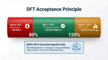
Individual readings fall slightly below minimum specified DFT but area average remains within tolerance.
This aligns with the 80/120 acceptance principle in SSPC-PA 2 (Level 3 default): individual spot measurements can fall to 80% of specified minimum or reach 120% of maximum, provided the overall area average meets the specified minimum. For concrete specifically, SSPC-PA 9 defines a spot measurement as the average of at least 3 readings taken within a 15 cm diameter circle.
Action: Flag location, apply light additional coat if required, re-measure.
Out-of-Spec (Too Thin)
Average readings below minimum specification increase risk of moisture penetration, carbonation, chemical attack, or rebar corrosion.
Action: Mark non-conforming area, apply additional coat per manufacturer's overcoat window, allow full cure, re-inspect before sign-off.
Out-of-Spec (Too Thick)
Readings that significantly exceed maximum specification introduce risks such as:
- Solvent entrapment during cure
- Internal stress cracking
- Adhesion failure or surface delamination
Action: Document, consult coating manufacturer for remediation guidance (removal and recoat vs. acceptance with monitoring), investigate application technique.
Common Errors in DFT Measurement on Concrete
Concrete's non-uniform surface drives most measurement errors — pores, aggregate peaks, and profile valleys all introduce variability that a single reading cannot capture. The errors below share a common fix: a systematic, multi-reading approach backed by the right equipment and technique.
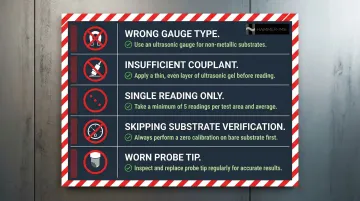
Using the Wrong Gauge Type
Applying magnetic induction or eddy current gauges (designed for metal) to concrete yields no valid reading or false results. These instruments require ferrous or non-ferrous metal substrates and will not function on non-metallic surfaces. Confirm the gauge is rated for concrete before beginning any measurement session.
Insufficient Couplant or Poor Probe Contact
Failing to apply adequate couplant on rough surfaces, or placing the probe at an angle rather than flat, introduces air gaps that disrupt the ultrasonic signal. This produces erratic low or zero readings. For rough or vertical surfaces, propylene glycol gel is essential; plain water works only on smooth horizontal surfaces.
Trusting Single Readings on Rough Surfaces
A single measurement over a pore, aggregate peak, or profile valley can deviate significantly from true film thickness. ASTM D6132 requires multiple readings per area and averaging to account for surface variability. SSPC-PA 9 specifies five spot measurements over each 10 m² area, with each spot being the average of at least 3 readings.
Skipping Verification on Uncoated Substrate
Before measuring coated areas, verify the gauge reads zero (or within tolerance) on bare concrete. Without this step, surface profile variability skews every reading that follows. Use an uncoated reference area for the baseline check, or apply the correction procedure specified in the relevant standard.
Neglecting Probe Tip Condition
A worn, dirty, or damaged probe tip produces lower or erratic readings. Check the probe tip before each session, clean it after every measurement point, and swap it out as soon as wear becomes visible.
Safety and Best Practices
Surface Preparation:
- Keep measurement areas clean and dry
- Debris, standing water, or wet coatings compromise acoustic contact and contaminate readings
Personal Protective Equipment:
- On active job sites or industrial floors, wear gloves, eye protection, and knee pads if measuring at floor level
- For coatings containing hazardous materials (lead-based or isocyanate-containing), follow site-specific chemical exposure protocols before scribing or touching surfaces
Production-Line Applications:
For large-scale coating of construction panels, boards, or prefabricated concrete elements, inline contactless measurement systems provide continuous monitoring without interrupting production flow. This removes the need for manual spot checks at high throughput volumes.
Hammer-IMS specialises in non-nuclear, non-contact measurement technologies that feed real-time thickness data back into the production process — allowing adjustments on the fly rather than after the fact.
Conclusion
Accurate DFT measurement on concrete comes down to three things done consistently:
- Choosing the right method for the substrate
- Applying consistent technique — couplant use, probe positioning, and multi-reading averaging
- Interpreting results against applicable standards, not individual data points
Both under-coated and over-coated concrete carry real consequences, from accelerated substrate deterioration to adhesion failure. A disciplined inspection routine protects asset longevity, ensures contractual compliance, and reduces long-term maintenance costs. With U.S. concrete repair costs reaching $18–21 billion annually, the cost of getting DFT measurement wrong far exceeds the effort of getting it right.
Frequently Asked Questions
What is the recommended dry film thickness?
Recommended DFT is defined by the coating manufacturer's product data sheet and project specification. Common protective coatings on concrete range from approximately 75 µm for thin latex paints to over 1,000 µm for heavy epoxy or polyurea systems. Always follow the specified minimum and maximum DFT for the exact product in use.
What is the 80/120 acceptance criterion for dry film thickness?
The 80/120 criterion in SSPC-PA 2 allows individual spot measurements to fall as low as 80% of the specified minimum or reach 120% of the maximum, as long as the overall area average meets specification. For concrete, SSPC-PA 9 defines each spot as the average of at least 3 readings within a 15 cm circle.
Can I use a magnetic induction gauge to measure DFT on concrete?
No. Magnetic induction and eddy current gauges require ferrous or non-ferrous metal substrates to function and will not produce valid readings on concrete, masonry, or other non-metallic surfaces. An ultrasonic gauge is the correct non-destructive choice for concrete.
What couplant should I use for ultrasonic DFT measurement on concrete?
Water-based propylene glycol gel is the most common couplant and works well on most concrete surfaces. Plain water can substitute on smooth, horizontal surfaces but may not provide adequate acoustic coupling on rough or porous concrete or vertical surfaces.
How many readings are needed for a valid DFT measurement on concrete?
ASTM D6132 and SSPC-PA 9 both require multiple readings because concrete surface variability makes single readings unreliable. SSPC-PA 9 specifies five spot measurements per 10 m², with each spot averaged from at least 3 readings; outliers from visible pores should be excluded per standard guidance.
What should I do if DFT readings vary widely across a concrete surface?
High reading variation on rough or porous concrete is normal. Increase the number of readings in that area, then calculate a localised average and compare it to specification. Extreme outliers from visible pores or profile peaks should be documented and excluded from the average per applicable standard guidance.