Introduction
Teflon (PTFE) coatings deliver non-stick, chemically resistant, and thermally stable properties across industrial applications — from chemical processing equipment to medical devices. Get the thickness wrong in either direction, and the consequences follow quickly: too thin risks substrate corrosion and premature wear, while excessive thickness invites cracking and delamination.
Accurate thickness measurement is essential for product performance, regulatory compliance, and safety. Research confirms that PTFE's non-conductive, non-magnetic nature means the right measurement method depends entirely on the substrate beneath the coating.
This guide covers the equipment you need, three primary measurement methods, how to interpret results correctly, and the most common errors to avoid — for both lab sampling and inline production monitoring.
Key Takeaways
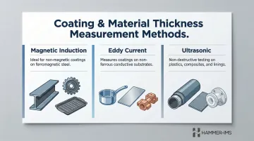
- Teflon coating thickness is measured using magnetic induction, eddy current, or ultrasonic gauges depending on the substrate
- Typical PTFE thicknesses range from 25 µm for consumer coatings to several hundred micrometres for heavy industrial applications
- Acceptance standards follow the 80/20 DFT rule (80% of readings ≥ minimum spec) or the stricter 90/10 rule (90%)
- Always calibrate on the actual substrate material—zero calibration on a different substrate introduces systematic error
- Inline contactless systems deliver consistent, non-destructive measurement for continuous materials like films and fabrics
What You Need to Measure Teflon Coating Thickness
Selecting the correct instrument depends entirely on the substrate beneath the Teflon coating — steel, aluminium, and plastic each require a different approach, and no single gauge works across all three.
Tools and Instruments Required
Core equipment varies by method but typically includes:
- Electromagnetic DFT gauge with appropriate ferrous or non-ferrous probe
- Eddy current gauge for non-magnetic metals
- Ultrasonic thickness gauge with low-frequency composite probe
- Calibration foils or reference standards of certified thickness
- Adequate lighting for visual pre-inspection of surface contamination
For production-line or continuous web applications (such as PTFE-coated fabrics, wire insulation, or laminated films), inline non-contact measurement systems replace handheld gauges entirely. These systems provide real-time feedback across the full material width without interrupting the process.
Preconditions and Setup
Before taking any measurements, surface condition directly affects accuracy. Prepare the substrate as follows:
- Clean the surface completely — dust, oil, or release agents between probe and surface cause false readings
- Verify the surface is dry before measurement
- Inspect for damage or roughness that may affect probe contact
Calibration is equally important and must use materials that match your actual production conditions:
- Zero the instrument on an uncoated sample of the exact same substrate material and geometry used in production
- A generic reference bar or foil that doesn't match your substrate introduces systematic measurement error
- For rough or blasted surfaces, apply correction values per ISO 19840 standards
Methods to Measure Teflon Coating Thickness
No single method works for every Teflon-coated substrate. The right technique depends on the substrate material — ferromagnetic steel, non-magnetic metal, or non-metallic — and whether you're measuring in a lab or inline during production.
The table below helps narrow down the correct approach before you reach for a gauge:
| Method | Substrate Type | Typical Application |
|---|---|---|
| Magnetic Induction | Ferromagnetic steel | Industrial components, bakeware |
| Eddy Current | Aluminium, stainless, copper | Cookware, precision parts |
| Ultrasonic | Plastics, composites, bulk PTFE | Pipes, linings, non-metallic parts |
Method 1: Magnetic Induction (For PTFE on Ferromagnetic Steel)
Magnetic induction measures the non-magnetic PTFE layer over ferromagnetic steel by detecting changes in a magnetic field between the probe and substrate. ISO 2178 specifies this method for non-magnetisable coatings on magnetisable base metals.
Tools Required:
- Electromagnetic DFT gauge with ferrous probe
- Calibration foils of known thickness
- Uncoated reference substrate of the same steel grade
Step-by-Step:
- Zero-calibrate the gauge on a clean, uncoated section of the same steel substrate. Apply calibration foils to verify accuracy before proceeding.
- Place the probe perpendicular to the coated surface with full face contact—no tilt or air gap. Take at least five readings per area in a defined pattern.
- Record all readings and calculate mean, minimum, and maximum values. Flag any readings below the specified minimum dry film thickness.
Best for: Steel substrates where speed and availability matter. This method is fast, reliable, and widely supported by off-the-shelf gauges. It cannot be used on aluminium, stainless steel, or non-metallic substrates, and results are sensitive to substrate roughness and magnetic property variation.
Method 2: Eddy Current Method (For PTFE on Non-Magnetic Metals)
The eddy current method measures PTFE coating thickness on non-ferrous metal substrates — aluminium, stainless steel, copper — by detecting changes in eddy currents induced in the conductive substrate below the coating.
Tools Required:
- Eddy current DFT gauge with non-ferrous probe
- Uncoated aluminium or stainless substrate of same alloy for calibration
- Certified calibration foils
Step-by-Step:
- Calibrate the eddy current gauge on an uncoated sample of the same non-ferrous substrate alloy. Different aluminium alloys have different conductivities and will affect readings if not properly matched.
- Apply the probe to the coated surface, maintaining consistent pressure and perpendicular orientation. Thin Teflon coatings on aluminium (common in cookware) require stable, flat contact points.
- Record multiple readings per test zone, checking for uniformity. Inconsistencies often indicate uneven spray application or coating voids.
Limitations: The right choice for aluminium cookware, stainless industrial parts, and copper-wound components. It becomes ineffective on non-metallic substrates or where the metal substrate is too thin to sustain a measurable eddy current response.
Method 3: Ultrasonic Thickness Measurement (For Bulk PTFE or Non-Metallic Substrates)
Ultrasonic gauges use high-frequency sound waves to measure through a PTFE layer by timing the echo return from the opposite surface. This approach suits plastic or composite substrates, or any application where the PTFE layer is thick enough to generate a clear echo.
Tools Required:
- Ultrasonic thickness gauge with low-frequency composite probe
- Ultrasonic couplant gel
- Reference block of known PTFE thickness for velocity calibration
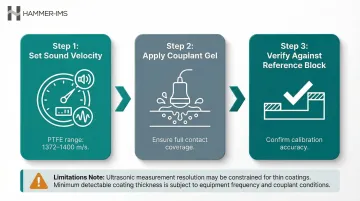
Step-by-Step:
- Set the sound velocity for PTFE in the gauge settings. PTFE's acoustic velocity ranges from 1372 to 1400 m/s—distinctly different from metals.
- Apply couplant gel to the probe face and press firmly against the PTFE surface. For thin coatings on non-metallic substrates, use a delay-line probe to improve near-surface resolution.
- Verify readings against a known PTFE reference block. Note that very thin PTFE coatings (below ~50 µm) may be at the resolution limit of standard ultrasonic gauges.
Limitations: Works well for non-metallic substrates and bulk PTFE pipes, sheets, or linings. Thin decorative or light industrial Teflon coatings on metal are often too thin for reliable ultrasonic detection. Couplant gel also makes this method impractical for high-volume or continuous production inspection.
How to Interpret Teflon Coating Thickness Results
A thickness reading only becomes meaningful when compared against the applicable specification—whether a product datasheet, customer standard, or regulatory requirement. Interpretation requires understanding acceptance rules and acting on deviations.
Normal/Acceptable Results
All readings meet or exceed the specified minimum DFT and fall within maximum tolerance. A narrow spread between minimum and maximum readings confirms uniform application. Document readings, accept the batch, and proceed to the next quality gate.
Understanding the 80/20 and 90/10 DFT Rules
Industrial coating acceptance relies on statistical rules that account for natural application variability:
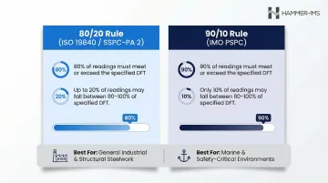
80/20 Rule (ISO 19840 and SSPC-PA 2):
- 80% of all individual readings must meet or exceed the specified minimum DFT
- No single reading may fall below 80% of the minimum specification
- Common in industrial and commercial protective coatings
90/10 Rule (IMO PSPC):
- 90% of all readings must meet or exceed the specified minimum DFT
- No single reading may fall below 90% of the minimum specification
- Required for marine environments (dedicated seawater ballast tanks)
Apply the rule your specification or customer contract mandates. When no rule is specified, default to 80/20 for general industrial work and 90/10 for any safety-critical or corrosive environment.
Minor Issues
A small number of readings fall marginally below spec but remain within the tolerance band permitted by the applicable DFT rule.
Actionable step: Assess whether localised recoating is feasible. Document the deviation and evaluate against end-use risk.
Out-of-Spec Results
Multiple readings fall below minimum DFT, or the average falls short, or individual readings drop below the absolute minimum (e.g., below 80% or 90% of spec).
Consequences:
- Risk of coating failure and substrate corrosion
- Chemical permeation through inadequate barrier thickness
- Adhesion loss or premature wear
- In food-contact applications, increased risk of regulated substance migration
What to do: Reject the batch for recoating or rework. Then investigate the application process for root cause — common culprits include:
- Inconsistent spray pattern or nozzle wear
- Incorrect cure temperature or dwell time
- Material viscosity outside the specified range
Inline Measurement for Continuous Production
For industrial production environments with continuous Teflon-coated materials (coated fabrics, wire insulation, PTFE-laminated films), inline measurement systems enable real-time thickness feedback. Contactless technologies — such as millimetre-wave (M-Ray) systems — flag deviations across the full production width without stopping the line or using contact probes, eliminating sampling gaps and reducing rework.
Actionable step: Where production speed or material sensitivity makes contact probing impractical, evaluate inline contactless gauging to shift from batch sampling to continuous coverage.
Common Errors When Measuring Teflon Coating Thickness
- Wrong calibration substrate — the most frequent error: zeroing on a reference bar that doesn't match the actual substrate (alloy type, roughness, thickness) causes systematic offset. Always zero on an uncoated piece of the exact part being tested.
- Poor probe contact: tilting the probe or losing full face contact introduces air gaps that inflate readings. On curved parts, use a probe with a contact radius matched to the geometry.
- Surface contamination: dust, release agents, or residual couplant adds false thickness. Clean and dry every surface before starting a measurement series.
- Mismatched measurement method: a magnetic induction gauge on an aluminium substrate — or an eddy current gauge on steel — produces invalid data. Confirm the substrate material before selecting the instrument.
- Edge and curvature effects: readings taken too close to a part edge or sharp radius are distorted by geometry. Follow the minimum standoff distance specified in the instrument's operating guidelines.
Safety and Best Practices
Safe measurement practice protects both operators and equipment. The three areas below cover the most common hazards when measuring Teflon coating thickness in production environments.
Inline Measurement Zones
- Confirm all moving-part guards are in place before measurement begins
- Operators must not reach into the measurement zone while machinery is active
High-Temperature Environments
- For freshly cured PTFE coatings measured directly after industrial ovens or post-cure stages, use heat-resistant gloves and appropriate face protection
Chemical Contamination
- Keep measurement instruments and calibration foils free of residue
- Cleaning solvents on parts can degrade probe contacts and calibration foil surfaces — wipe down contact surfaces before and after each measurement session
Conclusion
Accurate Teflon coating thickness measurement comes down to three factors working in alignment:
- Select the right measurement method for your substrate type
- Calibrate on the actual production substrate, not a substitute reference
- Interpret results against a defined specification, applying DFT rules where required
For high-volume or continuous production environments, inline non-contact measurement eliminates sampling gaps, reduces rework, and provides the real-time data needed to keep your process within spec.
Frequently Asked Questions
How do you measure Teflon coating thickness?
The method depends on the substrate: magnetic induction gauges are used on steel substrates, eddy current gauges on non-magnetic metals like aluminium, and ultrasonic gauges for thicker PTFE layers or non-metallic substrates. All require calibration on the actual production substrate.
How thick is a typical Teflon coating?
Light consumer coatings (e.g., cookware) typically start around 25 µm, whilst industrial PTFE coatings for chemical resistance or wire insulation can reach several hundred micrometres. Verify the target range against the applicable product specification before measuring.
What are the 80/20 and 90/10 DFT rules for Teflon coating thickness?
The 80/20 rule requires 80% of readings to meet minimum DFT, with no single reading below 80% of that minimum; the stricter 90/10 rule raises both thresholds to 90%. Both rules accommodate natural process variability without demanding every point hit full spec.
Can you measure Teflon coating thickness without damaging the surface?
Yes. Non-destructive methods — magnetic induction, eddy current, ultrasonic, and contactless inline systems — do not damage the coating. Destructive cross-section (metallographic) methods are reserved for lab sampling or failure investigation only.
What happens if Teflon coating is too thin or too thick?
Coatings that are too thin risk chemical permeation, substrate corrosion, premature wear, and — in food-contact applications — increased migration of regulated substances. Excessively thick coatings can suffer adhesion failure, cracking, or delamination. Either deviation requires process correction.
How often should Teflon coating thickness be measured in production?
Frequency depends on production volume and risk tolerance. At minimum, batch sampling at defined intervals is standard practice. For critical or high-volume applications, continuous inline measurement is recommended to catch process drift immediately and reduce scrap.