Introduction
Thermal spray coatings protect industrial assets from corrosion and wear — but thickness has to land in a precise range. Apply too little, and corrosion breaks through in months instead of decades. Apply too much, and residual stresses trigger cracking, adhesive failure, and dimensional non-conformance.
Research shows that while 200 µm of Thermal Spray Aluminum (TSA) can deliver 30+ years of splash-zone protection, excessive thickness shifts failure modes from manageable cohesive cracking to catastrophic delamination.
This guide covers:
- The measurement tools required for thermal spray inspection
- Three primary methods with step-by-step procedures
- How to interpret results against SSPC-PA2 compliance rules
- The most common errors that invalidate readings
Key Takeaways
- Choose your method by substrate: Magnetic Induction (carbon steel), Phase-Sensitive Eddy Current (non-magnetic), or Photothermal (rough or inline surfaces)
- Always calibrate on test coupons from the same substrate alloy — mismatched calibration causes systematic error
- Use methods that average over a larger area to avoid surface roughness inflating your readings
- SSPC-PA2 (80/20 rule) and the maritime 90/10 rule are separate standards — don't apply them interchangeably
- Use inline contactless measurement to catch thickness deviations in real time and cut material waste
What You Need to Measure Thermal Spray Coating Thickness
Four factors drive method selection: substrate magnetism, coating material type, surface geometry, and whether you're doing a spot-check or continuous production measurement. Getting these right before you pick up a gauge saves time and prevents calibration errors downstream.
Tools Required
Contact Gauges:
- Type 2 DFT gauge — magnetic induction method, suited for non-magnetic coatings on ferromagnetic substrates
- PSEC gauge (phase-sensitive eddy current) — for conductive coatings on non-magnetic substrates such as stainless steel
- Calibrated reference standards or certified plastic shims
- Test coupons matched to substrate alloy
Non-Contact Systems:
- Photothermal or optical thickness meter
- Calibration reference of known thickness
- Data logging interface or process control software
Accessories:
- Zero calibration plate
- Dial or digital micrometer for mechanical verification
- Measurement logs (electronic or paper)
Preconditions and Setup
CRITICAL: The calibration coupon must match the alloy of the structure you're measuring. Using a carbon steel coupon to calibrate for stainless steel structures creates false readings. ASTM B499 notes that magnetic permeability and electrical conductivity variations between calibration and test materials introduce severe bias.
Before measuring:
- Confirm the coated surface is clean and free of loose spray particles
- Remove contaminants that create false high readings
- Match substrate surface roughness on calibration coupons to actual parts
Methods to Measure Thermal Spray Coating Thickness
No single method suits every application. Substrate magnetism, surface roughness, and production environment dictate the correct approach.
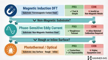
Method 1: Magnetic Induction (DFT Gauge)
Measures the distance between the probe tip and a ferromagnetic substrate through a non-magnetic coating. Valid only when the base metal is magnetically permeable (carbon steel, iron).
You'll need:
- Type 2 DFT gauge with appropriate probe
- Zero calibration plate
- Substrate test coupon (same alloy as structure)
- Certified calibration foils or shims
Steps:
- Zero calibration: Place the probe flat on bare, uncoated substrate (or calibration coupon) and perform zero calibration per manufacturer instructions
- Measurement: Position the probe perpendicular to the coated surface; press gently until the gauge beeps or locks
- Record and average: Take minimum five measurements per area per SSPC-PA2 and calculate the average
Fast, simple, and widely available. However, it cannot measure coatings on non-magnetic substrates—Type 304 or Type 316 austenitic stainless steel will return false or unusable readings.
Method 2: Phase-Sensitive Eddy Current (PSEC)
Uses alternating electromagnetic fields sensitive to phase shift caused by the coating layer. Effective for measuring thermally sprayed coatings on non-magnetic conductive substrates where magnetic induction fails.
Tools needed:
- PSEC gauge calibrated for the specific substrate alloy
- Calibration coupon of the same non-magnetic alloy (e.g., Type 316 stainless)
- Reference standards
Steps:
- Coupon preparation: Fabricate or source a calibration coupon from the same non-magnetic alloy as your structure—do not substitute carbon steel
- Calibration: Calibrate the PSEC gauge on the uncoated coupon surface; verify with known-thickness reference standard
- Measurement: Apply probe to coated structure at each location, record readings, and verify SSPC-PA2 compliance across required spots
Enables accurate TSA measurement on austenitic stainless steel. Less sensitive to substrate roughness, part curvature, and base metal composition variation than magnetic methods — making it more reliable for complex structures.
Method 3: Photothermal / Non-Contact Optical Measurement
A pulsed light source heats the coating surface by a few degrees Celsius for milliseconds. An infrared sensor tracks the time-dependent cooling curve to calculate coating thickness. Measurement takes under one second and tolerates rough sprayed surfaces.
Tools needed:
- Photothermal measurement device with optical probe
- Bore probes for confined geometries (if applicable)
- Calibration reference of known coating thickness
- Data logging interface
Steps:
- Positioning: Position the measurement probe at the specified standoff distance (adjustable from a few millimetres to approximately one metre); ensure spot diameter covers the specified area (typically 1–50 mm) to average roughness effects
- Trigger: Fire the light pulse; the device automatically records and analyses the thermal response curve
- Log results: For inline environments, connect to process control to enable real-time feedback. Contactless inline systems enable continuous, full-width monitoring and closed-loop coating thickness control.
Delivers 1–2% repeatability even on rough sprayed surfaces. It suits complex geometries and confined spaces, and supports inline production integration. Equipment costs are higher than contact gauges, and initial setup requires calibration with a reference sample.
How to Interpret Thermal Spray Coating Thickness Results
Every thickness reading leads to an accept/reject decision. Getting that decision wrong means either deploying under-protected parts or scrapping material needlessly — both outcomes that cost time and money.
Normal/Acceptable
Coatings that meet specified nominal thickness at all required measurement locations, with individual spot readings within the tolerance band.
Under SSPC-PA2, the 80/120 rule applies:
- No single spot measurement may be less than 80% of the specified minimum
- No single spot measurement may exceed 120% of the specified maximum
- Average of spot readings must meet minimum specified DFT
Example: For a 200 µm minimum specification:
- Minimum acceptable single reading: 160 µm (80% floor)
- Maximum acceptable single reading: 240 µm (120% ceiling, if specified)
- Average of all readings: ≥200 µm
Parts meeting these criteria proceed to the next production step.
Minor Issues / Slight Deviation
When readings fall slightly below the minimum but remain within acceptable tolerance, the applicable rule set determines whether a part passes or requires rework.
| Rule | Standard | Threshold |
|---|---|---|
| 80/20 Rule | SSPC-PA2 | No reading below 80% of minimum |
| 90/10 Rule | Maritime/IMO PSPC | No reading below 90% of minimum; 90% of readings must meet nominal DFT |
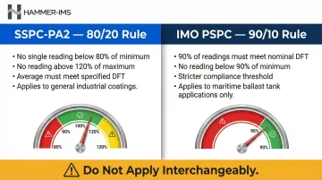
The 90/10 rule is stricter and applies only when specified contractually or for ballast tank applications. Do not default to 90/10 unless explicitly required.
When a minor deviation is confirmed, take these steps:
- Re-spray deficient areas
- Re-inspect after touch-up
- Document deviations and corrective measures
Out-of-Spec / Unacceptable
Readings below the 80% floor (or 90% threshold under stricter rules), or readings exceeding maximum specified thickness.
Consequences:
- Under-thickness: Insufficient corrosion or wear protection; premature failure
- Over-thickness: Risk of stress cracking, adhesion failure, dimensional non-conformance
Required actions:
- Re-spray under-thickness areas
- Strip and recoat if over-thickness risks adhesion failure
- Formal non-conformance reporting per quality system
- Root cause analysis to prevent recurrence
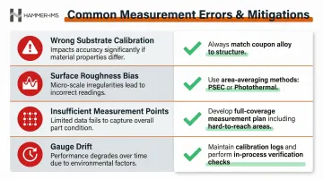
Common Errors and Best Practices for Thermal Spray Coating Measurement
Calibration on Wrong Substrate Material
Using a carbon steel coupon to calibrate a gauge that will measure coatings on stainless steel introduces severe systematic error. Magnetic permeability and electrical conductivity variations between materials invalidate readings. Always match calibration coupon alloy to the actual structure.
Surface Roughness Bias
Rough, grit-blasted or as-sprayed surfaces cause contact probes to rest on asperity peaks rather than the true average surface. This creates artificially high readings.
Mitigation strategies:
- Use methods that average over larger measurement areas (PSEC, photothermal)
- Take multiple readings per spot and discard outliers
- Select gauges designed to minimise roughness sensitivity
Insufficient Measurement Points
Taking too few readings or concentrating measurements in easy-access flat areas misses systematic thickness variations. Complex geometries, edges, bore walls, and areas near fixtures often have different coating thicknesses.
Best practice:
Develop a measurement plan that maps all critical areas, including hard-to-reach locations.
Gauge Drift and Verification Failures
Gauge drift can invalidate entire batches of results if not caught early. To stay ahead of it:
- Maintain a calibration log with timestamps and reference values
- Perform in-process verification checks at defined intervals during long inspection runs
- Replace or recalibrate gauges immediately when drift exceeds tolerance
Manual Spot-Checking Limitations
In production environments, manual spot-checking introduces human variability and slows throughput. Inline, real-time measurement solutions with data logging and automated process feedback address both problems — cutting over-spray waste and stopping under-protected parts before they reach assembly.
Frequently Asked Questions
How do you measure thermal spray coating thickness?
The three primary methods are magnetic induction DFT gauges (for magnetic substrates like carbon steel), phase-sensitive eddy current (for non-magnetic substrates like austenitic stainless steel), and photothermal/optical methods (for rough surfaces and production environments). Method choice depends on substrate type and required accuracy.
What is the typical thickness of thermal spray coatings?
Corrosion protection coatings (TSA/TSZ) typically range from 100–350 µm, with NORSOK M-501 specifying 200 µm for TSA and 100 µm for TSZ. Wear-resistant carbide coatings range from 50–500 µm, while thermal barrier coatings for gas turbines typically span 100–500 µm.
What are the common DFT rules (80/20 and 90/10) for thermal spray coatings?
The 80/120 rule (SSPC-PA2) requires no single spot reading below 80% of minimum or above 120% of maximum. The 90/10 rule (IMO PSPC) is stricter: 90% of readings must meet nominal DFT, and no reading may fall below 90% of minimum, making it the standard for maritime ballast tank applications.
Can you measure thermal spray coating thickness without damaging the coating?
Yes. Multiple non-destructive methods exist, including eddy current, magnetic induction, and photothermal techniques. All measure coating thickness without cutting, sectioning, or otherwise damaging the coating or substrate.
What is the best method for measuring thermal spray coatings on non-magnetic stainless steel?
Phase-sensitive eddy current (PSEC) is the recommended method for TSA and similar coatings on austenitic (non-magnetic) stainless steel alloys. Standard magnetic DFT gauges cannot produce valid readings on non-magnetic base metals.
How does surface roughness affect thermal spray coating thickness measurements?
The rough, grit-blasted or as-sprayed surface causes contact probe gauges to rest on surface peaks rather than the true average thickness plane, leading to inflated readings. Area-averaging techniques like PSEC and photothermal methods significantly reduce this error.