Introduction
Coating defects — whether streaks on a film line, pinholes in a nonwoven, or uneven thickness on a plastic sheet — can silently destroy batch quality, trigger customer returns, and force costly production shutdowns long before anyone catches them.
The difference between a recoverable incident and a full line stoppage often comes down to one thing: matching the right detection method to the right defect type.
According to industry research, undetected coating defects cost manufacturers up to 5% of material output in giveaway and scrap, representing millions in wasted raw materials annually across sectors from textiles to plastics. Early, accurate detection is what separates a controlled quality incident from a full production loss. This guide covers the primary detection methods — visual inspection, automated optical systems, thickness-based measurement, and more — so you can identify which approach fits your process and defect profile.
Key Takeaways
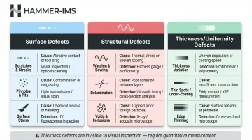
- Coating defects fall into three categories: surface defects, structural defects, and thickness/uniformity defects
- Detection methods range from manual stroboscopic inspection to automated camera systems, laser scanning, and non-contact thickness measurement
- Defect maps showing machine-direction and cross-direction patterns are critical diagnostic tools for tracing root causes
- A systematic five-step process — detect, map, diagnose, correct, verify — reduces both defect recurrence and material waste
- Real-time, in-line measurement systems connect defect detection directly to process correction — cutting response time and scrap
What Are Coating Defects and Why Do They Occur?
Coating defects are deviations from the intended surface, thickness, or structural uniformity of an applied coating layer. They occur across continuous web processes, sheet-based production, and spray or roll coating applications — anywhere a liquid or semi-liquid layer is applied to a substrate and then cured or dried.
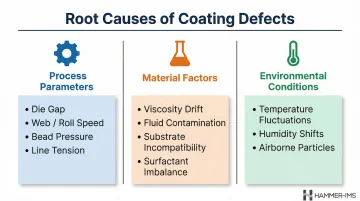
Three primary causes drive most coating defects:
- Incorrect die gap settings, mismatched web and roll speeds, improper bead pressure, or unstable line tension
- Viscosity drift, fluid contamination, incompatible substrates, or surfactant imbalance in the coating material
- Temperature fluctuations, humidity shifts, and airborne particles settling onto wet coatings
Many defects are invisible to the naked eye at production speeds or require specific lighting angles to detect. Surface irregularities under 50 microns, thickness variations with no visible signature, and machine-direction repeating patterns from roll contamination often go unnoticed without systematic inspection. Manual quality checks alone cannot reliably catch these defects at production speeds.
Common Types of Coating Defects, Their Causes, and Fixes
Each defect type has a distinct visual signature, a likely cause, and a standard corrective action. Knowing all three is what makes a quality control programme effective.
Surface Defects: Streaks, Scratches, and Pinholes
Streaks appear as long continuous marks running in the machine direction. They typically originate from contamination lodged in the die gap, nicks or damage to die lips or doctor blades, or air bubbles trapped in the coating bead.
Standard fixes:
- Purge coating lines to clear contamination
- Inspect die lips for nicks, burrs, or wear
- Reset die gap to specification
- Retrieve a defect map to confirm the transverse-direction position and lane affected
Pinholes are tiny spots — often sub-100 micron — where the coating layer is entirely absent. Causes include contamination rupturing the liquid film as it's applied, particles on the substrate surface, or drying stresses that pull the coating away from local defects.
Cures include:
- Improved substrate cleaning before coating application
- Finer filtration of the coating fluid (for example, upgrading from 50-micron to 25-micron filters)
- Controlled drying profiles that reduce thermal stress gradients
Scratches are narrow, ragged-edged linear gouges caused by contamination on a contact roll or a speed differential between the roll and the moving web. To fix: clean all rolls in contact with the web and confirm roll speeds are matched to the web speed.
Structural Defects: Chatter, Blistering, and Bubbles
Mechanical chatter appears as straight, transverse-direction bars repeating at regular intervals. It's caused by vibrations transmitted from pumps, drives, or coating equipment directly to the coating bead.
Serpentine chatter presents as irregular TD waves and results from hydrodynamic instability when the process operates outside its stability window (for example, coating speed too high for the fluid viscosity).
The two types look similar visually but have distinct machine-direction signatures on a defect map. Mechanical chatter shows a fixed repeat distance corresponding to pump frequency; serpentine chatter shows variable spacing.
Blistering and bubbling occur when trapped moisture or gases beneath the coating expand during drying. Macrobubbles and microfoam may result from surfactant imbalance or aggressive mixing that entrains air into the coating formulation.
Fixes typically involve:
- Pre-drying the substrate to remove residual moisture
- Adjusting coating formulation to reduce surfactant concentration or air entrainment
- Controlling drying-zone temperatures to prevent rapid outgassing
Thickness and Uniformity Defects
Uneven coating weight or thickness (thin spots, thick bands, cross-direction variation) may not produce a visible surface defect but still compromises performance. Each of the following depends directly on consistent coating thickness:
- Barrier properties in packaging films
- Adhesive strength in laminates
- Thermal insulation in construction materials
Because these defects are invisible to the eye, they require quantitative measurement rather than visual inspection alone. A coating layer varying by ±10% in thickness may pass visual inspection but fail functional testing downstream.
Methods for Detecting Coating Defects
No single method detects every defect type. Effective inspection programmes use a layered combination of techniques matched to defect sensitivity requirements and production speed.
Manual Visual Inspection with Stroboscopic Systems
Stroboscopic lights synchronise with web speed to create a virtual freeze-frame effect, making defects visible to the human eye at high line speeds. The strobe flashes at the same rate as the web moves past the inspection station, effectively "stopping" the motion for visual review.
Best-use cases:
- Colour inconsistencies
- Streaks and bubbles
- Edge defects and web tracking issues
Limitation: Consistency depends on operator skill and lighting angle, and sub-50-micron defects are typically missed. Manual inspection is also subject to fatigue, especially on long production runs.
Automated Camera and Laser Vision Systems
Two detection modes cover the full range of surface defects:
- Bright field: Detects defects that change light intensity — pinholes, voids, and stains
- Dark field: Detects defects that scatter or diffuse light — scratches, gels, and dimples
AI-driven classification software assigns defect types, calculates size parameters, logs defect locations per roll, and triggers alarms for pre-defined conditions such as repeat patterns or defect density thresholds. Laser systems excel at dark field detection and can resolve defects smaller than 50 microns, whilst camera systems provide superior grey-scale imaging and colour analysis for broader defect categories.
System design must be matched to the optical nature of the target defect. A dark-field laser scanner suits scratch detection on transparent films; a bright-field camera system is better suited for detecting voids in opaque coatings.

Non-Contact Thickness and Basis Weight Measurement
Visual-only inspection cannot catch coating weight variation or cross-direction thickness drift. These defects are invisible to cameras yet directly affect product performance and yield. Contactless measurement systems using millimeter-wave or microwave technology scan the full web width in real time, detecting thickness non-uniformity and enabling immediate closed-loop process corrections without physical contact or nuclear sources.
Hammer-IMS's M-Ray platform achieves measurement accuracy down to 1 gram per square metre for basis weight or 1 micrometre for thickness, operating at measurement rates exceeding 3 kHz at web speeds up to 500 metres per minute.
Unlike optical systems, M-Ray technology is unaffected by material colour, transparency, or opacity — making it well-suited for heavily pigmented coatings containing barium sulphate, titanium dioxide, or calcium carbonate fillers.
Thermal and Hyperspectral Imaging
Thermal cameras detect temperature-based anomalies like poor adhesion zones or drying non-uniformity. A cold spot on a drying web may indicate insufficient heat transfer or excessive coating thickness preventing solvent evaporation.
Hyperspectral and multispectral imaging reveal chemical composition variations, optical brightener distribution, and coating coverage uniformity not visible in standard light. These systems are particularly valuable where functional additives must be distributed uniformly — coated paper, technical textiles, and nonwoven substrates are common applications. Key use cases include:
- Mapping optical brightener distribution across web width
- Detecting localised coverage gaps in functional coatings
- Identifying chemical composition variations linked to raw material inconsistency
A Step-by-Step Process for Coating Defect Detection and Resolution
This section translates the above methods into a practical, repeatable workflow for operators and process engineers. The most common failure is detecting a defect without tracing it to a root cause and verifying the fix.
Step 1 – Identify and Classify the Defect
Determine defect type (surface, structural, or thickness), visual characteristics, and approximate frequency using on-line inspection alarms and initial visual review.
Correct classification drives the correct diagnostic path. Misidentifying dimples as roll repeats or chatter as streaks wastes troubleshooting time. Use a standardised defect classification guide with reference images to ensure consistency across shifts and operators.
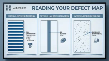
Step 2 – Map Defect Location and Recurrence Pattern
Use machine-direction (MD) and transverse-direction (TD) defect maps to determine whether the defect is repeating, lane-specific, or random.
Key diagnostic patterns:
- Repeating MD pattern: roll contamination — the repeat distance matches the circumference of the contaminated roll
- Lane-specific TD pattern: die geometry issue, such as a nicked lip or blocked die slot
- Random distribution: material or environmental cause, such as viscosity drift or airborne contamination
The machine-direction repeat distance is a critical diagnostic tool. A streak that repeats every 1.2 metres on the web corresponds to a contaminated roll with a 1.2-metre circumference — allowing you to identify which roll in the coating system is the source.
Step 3 – Trace the Root Cause
Cross-reference defect location data with process variables: die gap, coating speed, substrate condition, fluid viscosity, drying temperature.
Streaks, for example, may result from both contamination and a nicked die lip. Applying multiple fixes simultaneously — cleaning the die and adjusting the gap — makes it impossible to determine which action resolved the problem.
Document baseline process parameters before making changes. Then adjust one variable, measure the result, and proceed.
Step 4 – Apply Corrective Action and Adjust
Execute the targeted fix based on the root cause identified in Step 3. Apply corrections one at a time to confirm cause-and-effect relationships.
Common corrective actions include:
- Purging lines to clear contamination
- Cleaning or replacing rolls
- Adjusting die gap or lip geometry
- Modifying the drying temperature profile
On-line inspection systems provide immediate feedback on whether the defect count drops following each corrective step. If the defect persists after the first correction, the next variable in the diagnostic sequence can be addressed without waiting for offline analysis.
Step 5 – Verify the Fix and Close the Loop
Confirm defect resolution using the same detection system used in Step 1. Log corrective action, defect metrics before and after, and any process parameter changes.
Documentation builds a defect knowledge base that shortens diagnosis time in future occurrences. Closed-loop feedback systems take this further — measurement data feeds directly back to coating equipment, automatically correcting deviations before defective material accumulates.
How Hammer-IMS Can Help With Coating Quality Control
Hammer-IMS produces non-contact, non-nuclear measurement systems that use M-Ray (millimeter-wave) technology to scan coated webs in real time. They detect thickness non-uniformity, coating weight variation, and cross-direction drift — the defects that visual inspection systems miss entirely.
M-Ray systems feed continuous measurement data directly into the production process via Connectivity 3.0 software, enabling automatic correction of coating parameters before out-of-spec material accumulates. This tightens production tolerances and eliminates the delay between a defect appearing and any corrective action.
In textile coating, for instance, Hammer-IMS systems have been deployed with closed-loop feedback to coating knife controls, maintaining consistent basis weight without manual intervention. In battery film production, M-Ray measures coating layers on metallic substrates where optical methods fail due to opacity and surface reflectivity.
Industries where M-Ray coating measurement is actively deployed:
- Textiles: latex coating on artificial grass and coated fabrics
- Nonwovens: adhesive layer uniformity and basis weight control
- Plastic films: barrier coating thickness in packaging materials
- Construction materials: acoustic insulation and vapour barrier coatings
These are environments where high production speeds and harsh conditions make contact-based or nuclear measurement methods either impractical or off-limits — exactly where M-Ray technology operates without issue.
Frequently Asked Questions
What are the most common types of coating defects in industrial manufacturing?
The three main categories are surface defects (streaks, pinholes, scratches), structural defects (chatter, blistering, bubbles), and thickness/uniformity defects. Each requires a different detection approach: visual inspection for surface defects, process analysis for structural defects, and quantitative measurement for thickness variations.
What causes streaks in a continuous web coating process?
Streaks are primarily caused by contamination in the die gap, nicked or worn die lips, and air bubbles in the coating bead. A transverse-direction defect map can pinpoint the exact lane and die position responsible, allowing targeted corrective action rather than full system cleaning.
What is the difference between bright field and dark field defect detection?
Bright field detects defects that change light intensity (pinholes, voids, stains), whilst dark field detects defects that scatter or diffuse light (scratches, gels). Most industrial inspection systems combine both channels to capture the full range of surface defects.
How can coating thickness variation be detected if it's not visible to the naked eye?
Non-contact measurement systems using millimeter-wave, microwave, or terahertz technology scan the full web width and quantify thickness non-uniformity, even where no visible defect exists. They measure down to micrometre resolution and deliver real-time feedback to coating equipment.
How does real-time defect detection support closed-loop production control?
On-line measurement systems feed continuous data back to the coating process, enabling automatic adjustment of die gap, coating speed, or application weight before defective material accumulates. This reduces waste, improves consistency, and eliminates the delay between defect detection and corrective action.
What is the best way to prevent recurring coating defects?
Build a diagnostic knowledge base by combining defect classification, pattern mapping, and documented corrective actions. Pair visual inspection with real-time thickness measurement, and use closed-loop feedback to catch deviations before they reach quality thresholds.