Introduction
A coating failure discovered after delivery costs far more than one caught during inspection. Global corrosion costs reach $2.5 trillion annually, yet proper corrosion management systems can save 15–35% of those costs. An analysis of 130 industrial coating failures found that 45% stemmed from applicator errors like improper DFT application, and qualified inspectors were absent in 30% of failure cases.
Knowing where inspections fail is the first step to fixing them. This guide covers the tools, step-by-step methods, and result-interpretation criteria for inspecting painted surfaces properly — both manual and instrumental approaches — to prevent costly rework and premature failures.
Key Takeaways
- Visual inspection requires controlled lighting (1,000–4,000 lux per ISO 3668), 45° viewing angles, and reference standards to reliably detect defects
- Use substrate-specific thickness gauges: magnetic for steel, eddy current for non-ferrous metals, ultrasonic for plastics
- Colour and gloss need quantification via colorimeter and gloss meter; adhesion testing uses the cross-cut method
- Always compare results against manufacturer specifications: SSPC-PA 2 requires spot readings ≥80% of minimum DFT and area averages ≥100%
- Common errors: poor lighting, skipping calibration, measuring before full cure, and confusing WFT with DFT
What You Need to Inspect Painted Surfaces
Selecting the right tools and setting up the correct inspection environment before starting is critical. Incorrect setup produces unreliable readings no matter how carefully you apply the method itself.
Tools and Instruments Required
Core instruments needed across all three inspection methods include:
- Inspection lamp: High-CRI LED or fluorescent (D65 illuminant, 1,000–4,000 lux)
- Reference panels: Approved colour and texture standards
- Wet Film Thickness (WFT) gauge: Comb-style for in-process control
- Dry Film Thickness (DFT) gauge: Type depends on substrate (see table below)
- Gloss meter: Multi-angle (20°/60°/85°) per ISO 2813
- Colorimeter or spectrophotometer: For L*a*b* colour measurement
- Cross-cut adhesion test kit: Cutting knife, brush, and adhesive tape per ISO 2409
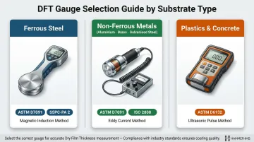
Substrate-to-Gauge Matching Table:
| Substrate Type | DFT Gauge Technology | Applicable Standards |
|---|---|---|
| Ferrous steel | Magnetic induction or pull-off | ASTM D7091, ISO 2808, SSPC-PA 2 |
| Non-ferrous metals (aluminium, brass, galvanised steel) | Eddy current | ASTM D7091, ISO 2808 |
| Plastics & concrete | Ultrasonic | ASTM D6132, ISO 2808 |
Preconditions and Setup
Inspection environment:
ISO 3668 requires 1,000–4,000 lux with D65 illuminant (quality class BC or better). Position panels at 500 mm viewing distance and assess at a 45° angle to the illumination direction. Deviating from these conditions most often causes orange peel, sagging, and colour variation to go undetected.
Surface state:
Beyond the environment, the coating itself must be ready. It should reach full cure per the manufacturer's specified dry time before any DFT measurement or adhesion testing. Measuring too early yields inaccurate thickness readings and risks damaging the film — partially cured coatings compress under the probe, producing artificially low values.
Methods to Inspect Painted Surfaces
A complete inspection typically requires three complementary methods used in sequence—visual assessment first, followed by thickness measurement, then surface attribute testing—since no single method reveals all quality parameters.
Method 1: Visual Inspection (Subjective Assessment)
Visual inspection identifies surface defects visible to the naked eye—runs, sags, pinholes, orange peel, craters, dust inclusions, colour non-uniformity, and gloss inconsistency—by evaluating the painted surface under controlled lighting at standardised distances.
Tools needed:
- High-CRI inspection lamp (LED or fluorescent, D65)
- Reference colour/texture panel
- Clean lint-free cloth
Step-by-step:
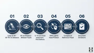
- Position the lamp at 45° to the surface; begin at 60-90 cm to assess large-area defects (runs, sags, colour bands)
- Move to 30 cm for medium-scale faults (orange peel, craters)
- Finish at 5-10 cm for fine defects (pinholes, micro-scratches, dust particles)
- Keep your head fixed while moving the light laterally and vertically, then swap—move your head while keeping the light fixed—to reveal defects that only appear at specific reflection angles
- Compare to the approved reference panel for colour, gloss, and texture acceptability
- Document all deviations with location and description
Pros & cons:
Fast and requires minimal equipment; essential for initial screening and full-surface coverage. However, results are subjective and inspector-dependent—standardised viewing conditions and written acceptance criteria are required to ensure consistency between operators.
Method 2: Coating Thickness Measurement
Coating thickness measurement verifies dry film thickness (DFT) against manufacturer specifications and project requirements. Wet film thickness (WFT) checks during application provide additional in-process control.
Tools needed:
- WFT comb gauge (during application)
- DFT gauge (magnetic, eddy current, or ultrasonic depending on substrate)
- Certified calibration standards for the gauge type
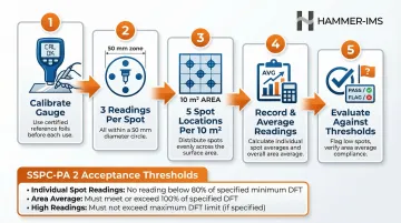
Step-by-step:
- Calibrate the DFT gauge using certified reference foils on a bare substrate of the same type and thickness as the production part—record calibration values before starting
- Take minimum three measurements per spot location (within a 50 mm diameter circle) and average them
- Select measurement spots randomly but geometrically representative of the full surface—SSPC-PA 2 recommends five spot measurements per 10 m² area
- Record all readings and calculate the average DFT per area
- Flag any spot reading below 80% of specified minimum; verify area average meets 100% of specified DFT per SSPC-PA 2 acceptance criteria
Pros & cons:
Calibrated correctly, DFT gauges deliver objective, repeatable results — the accepted benchmark for specification compliance verification. Manual spot-measurement is time-consuming for large production runs. For continuous industrial environments, contactless inline thickness measurement systems enable real-time DFT monitoring across the full production width without stopping the line.
Method 3: Surface Attribute Testing (Colour, Gloss, and Adhesion)
Surface attribute testing quantifies three objective quality parameters: colour consistency measured via L\*a\*b\* colour space and delta E, gloss level in gloss units, and coating adhesion strength via cross-cut classification. Together, these provide documented, comparable data for quality sign-off.
Tools needed:
- Colorimeter or spectrophotometer with reference data
- Gloss meter (multi-angle if required)
- Cross-cut adhesion test kit (cutting knife, brush, adhesive tape) per ISO 2409
Step-by-step:
Colour:
- Calibrate the colorimeter against its white reference tile
- Measure the painted surface at defined locations and compare L\, a\, b\* values against the approved master
- Calculate delta E (ΔE)—ASTM D2244 recommends using the CIEDE2000 formula for differences in the 0-5 range
- Apply acceptance thresholds (exact limits vary by specification):
- ΔE 0–0.5: imperceptible
- ΔE 1.0–2.0: acceptable for most industrial applications
- ΔE above 2.0–4.0: typically rejectable — AAMA 2605 allows ΔE ≤ 5; MIL-PRF-22750 requires ΔE ≤ 2.0–3.0
Gloss:
- Measure gloss level in GU (gloss units) at the specified angle—start with 60° per ISO 2813
- If the 60° reading exceeds 70 GU, remeasure at 20° (high gloss)
- If the 60° reading is below 10 GU, remeasure at 85° (low gloss/matte)
- Compare against the specification
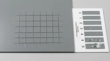
Adhesion:
- Using the cross-cut kit, make a grid of parallel cuts through the coating to the substrate
- Grid spacing depends on coating thickness: 1 mm for coatings ≤60 µm, 2 mm for 61-120 µm, 3 mm for 121-250 µm
- Brush away debris, apply adhesive tape firmly, then remove it with a sharp pull at 60° angle
- Classify the remaining grid from Gt 0 (no detachment—excellent) to Gt 5 (severe detachment)
- Document with photographs
Pros & cons:
Provides objective, traceable data required for formal quality documentation and customer compliance; identifies adhesion failures before the product reaches the field. Adhesion testing is destructive and cannot be performed on every part: it is typically used on sample parts or test coupons within each production batch.
How to Interpret Inspection Results
Misreading results—or applying the wrong acceptance standard—is as costly as performing no inspection at all. Consequences range from passing a defective batch to incorrectly rejecting good production.
Normal / Acceptable
Surface free of visible defects under standardised inspection
DFT spot readings ≥80% of specified minimum, area average ≥100% of specified minimum per SSPC-PA 2
Delta E within approved tolerance (typically ≤2.0 for industrial applications)
Gloss within ±specification range
Adhesion classification Gt 0 or Gt 1
Actionable step: Release the batch for next process stage and document readings.
Minor Issues / Borderline
Slight DFT shortfalls on isolated spots (but area average still compliant)
Delta E readings at the boundary of tolerance
Gt 2 adhesion on test samples
Minor surface texture inconsistencies visible only at close range under strong light
Next step: Investigate root cause — check application settings, ambient conditions, and substrate prep. Apply a corrective stripe coat or recoat if within the pot-life window, then re-inspect before release.
Out-of-Spec
DFT area average below 100% of specified minimum, or individual spots below 80%
Delta E clearly exceeds tolerance
Adhesion classified Gt 3 or worse
Widespread visible defects (pinholes, runs, craters) across the surface
Actionable step: Quarantine the affected parts and conduct root-cause analysis across four failure categories: surface preparation, ambient conditions, coating material, and application quality. From there, determine whether rework, recoating, or scrapping is the appropriate path forward.
Common Errors and Best Practices
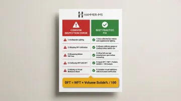
These are the five most common inspection mistakes that lead to coating failures in the field — and the best practices to prevent them.
Inspecting under inadequate or inconsistent lighting:
The single most common cause of missed defects in visual inspection. Always use a calibrated inspection environment with defined lux levels (1,000–4,000 per ISO 3668) and lamp type — never rely on ambient workshop lighting alone.
Failing to calibrate DFT instruments:
Uncalibrated gauges produce systematically skewed readings that can pass out-of-spec parts or reject compliant ones. Build calibration verification into the inspection procedure as a mandatory first step before each measurement session or after changing substrate type.
Measuring DFT before the coating has reached full cure:
Wet or partially cured films compress under the probe and give artificially low readings. Always verify elapsed cure time against the manufacturer's data sheet before taking thickness measurements.
Confusing wet film thickness (WFT) with dry film thickness (DFT):
The two are related by volume solids content but are not interchangeable. The formula is: DFT = WFT × (Volume Solids % / 100). As solvents evaporate during cure, the film shrinks — meaning WFT alone cannot confirm final compliance. Post-cure DFT is the required measurement for acceptance.
Relying on final visual walkdown alone:
A surface that looks acceptable during the final check may still have insufficient thickness, poor adhesion, or substrate moisture issues that will cause premature coating failure. Best practice is to inspect at each process stage: surface prep, application, and cure.
Conclusion
Accurate, structured inspection of painted surfaces requires more than a single check. A complete quality assurance approach combines three distinct methods:
- Visual assessment to identify surface defects and coating condition
- Instrumental thickness measurement to verify dry film thickness against specification
- Objective surface attribute testing to evaluate adhesion, hardness, and gloss
The value of inspection lies not just in catching defects, but in generating reliable process data that enables corrective action before failures propagate through a production run.
Results must always be interpreted against defined specifications and industry standards like SSPC-PA 2 or ISO 19840, not subjective judgement. Applying the methods and acceptance criteria in this guide consistently is what separates reactive defect-finding from proactive quality control — the difference between fixing failures and preventing them.
Frequently Asked Questions
What should you inspect for after painting?
Inspect for visible defects (runs, pinholes, craters, colour variation, gloss inconsistency), dry film thickness compliance using calibrated gauges, and adhesion strength via cross-cut testing. Compare all findings against the approved specification and reference standard, not subjective judgement.
Do home inspectors look at paint?
Home inspectors assess paint condition for signs of peeling, cracking, moisture damage, or lead paint hazards. They do not perform instrumental coating quality inspection (DFT, gloss, colour measurement) as used in industrial settings. Their focus is structural integrity and safety, not specification compliance.
What tools are used to measure the dry film thickness of paint?
There are three main DFT gauge types: magnetic induction (for ferrous steel), eddy current (for non-ferrous metals like aluminium and brass), and ultrasonic (for plastics and cementitious surfaces). Each must be calibrated on a representative bare substrate using certified reference foils before use.
What is the difference between wet film thickness and dry film thickness?
WFT is measured immediately after application using a comb gauge, while DFT is measured after cure. DFT is lower than WFT because volatile solvents evaporate during drying. The ratio is determined by the coating's volume solids content: DFT = WFT × (Volume Solids % / 100).
How do you test paint adhesion on a surface?
The cross-cut test (ISO 2409) involves cutting a grid through the coating to the substrate using a multi-blade knife, then applying and sharply removing adhesive tape. The remaining pattern is classified from Gt 0 (no detachment) to Gt 5 (complete detachment), with grid spacing determined by coating thickness.
What is an acceptable colour variation (delta E) in industrial paint inspection?
Delta E of 0–0.5 is imperceptible, 1.0–2.0 is acceptable for most industrial applications, and above 2.0–4.0 is typically considered a visible and rejectable difference. Exact thresholds must be agreed between customer and supplier and documented in the inspection specification before work begins.