Introduction
Calendering is a high-speed, high-pressure manufacturing process where micron-level thickness deviations translate directly into defective products, material waste, and failed quality specifications. At speeds exceeding 1000 m/min and compression forces reaching 300 tons, even slight roller misalignment or thermal drift can push thickness profiles outside tolerances—resulting in rejected batches or downstream failures in critical applications like battery electrodes and tire construction.
These consequences make thickness measurement the central discipline of calender line quality control. This guide covers the most widely used measurement techniques, the real-world challenges of measuring on fast-moving lines, and practical tips to get reliable data from any system.
Key Takeaways
- Calender roll deflection and thermal expansion create cross-web thickness profiles requiring sub-micron control
- Multiple non-contact technologies exist: laser triangulation, chromatic confocal, millimeter wave (M-Ray), and ultrasonic
- Full-width scanning detects variations that single-point sensors miss entirely
- Closed-loop integration with roll gap actuators cuts waste and reduces thickness drift in real time
- Non-nuclear alternatives like M-Ray avoid regulatory burdens while maintaining accuracy
Why Thickness Uniformity Matters in the Calendering Process
Roll Gap Settings Determine Product Quality
Calender roll gap settings directly determine output thickness, but achieving target specifications is complicated by mechanical realities. Roll separating forces cause rolls to bow apart at the center, requiring precision-ground crowns to compensate. Premium grinding tolerances of ±4 µm are necessary to minimize cross-machine direction (CD) variation.
Thermal expansion compounds the problem: temperature variations across the roll face—including the "oxbow effect" caused by differing thermal expansion coefficients in chilled iron—create localized diameter changes that shift thickness profiles dynamically during production.
Even minor deviations create serious problems. A Six Sigma analysis at an EPDM rubber facility documented a 29% reduction in CD thickness variation simply by refurbishing calender rolls to profile deviations no larger than 0.0002 inches (±5 µm).
Material feed inconsistencies, roller wear over time, and vibration from the calender frame further contribute to thickness variability that only continuous measurement can detect.
Direct Business Consequences of Poor Thickness Control
Poor thickness control creates cascading costs across production:
- Over-gauging drives material waste directly. The EPDM rubber facility referenced above saved an estimated $4,000 per day after reducing average thickness profiles by just 0.001 inches through improved roll geometry.
- Under-gauging produces out-of-spec material that fails quality inspections. In battery electrodes, deviations affect energy density; in rubber sheets for tires, non-uniformity compromises structural integrity.
- Reactive process control — relying on periodic offline spot checks — means defects accumulate before anyone catches them, making it nearly impossible to maintain tight production margins or respond quickly to process drift.
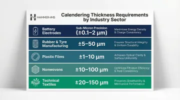
Industry-Specific Tolerance Requirements
Different sectors demand varying levels of precision:
- Battery electrodes: Sub-micron repeatability required; thickness governs energy density
- Rubber sheets (tyre manufacturing): Uniformity affects structural integrity and performance
- Plastic films: Consistency critical for optical clarity and mechanical properties
- Nonwovens: Basis weight and thickness uniformity determine filtration efficiency and texture
- Technical textiles: Coating thickness directly impacts waterproofing and breathability
Meeting these tolerances consistently — across the full web width, at line speed — is what drives the need for continuous, automated thickness measurement rather than periodic manual checks.
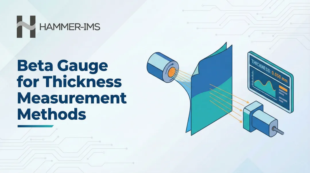
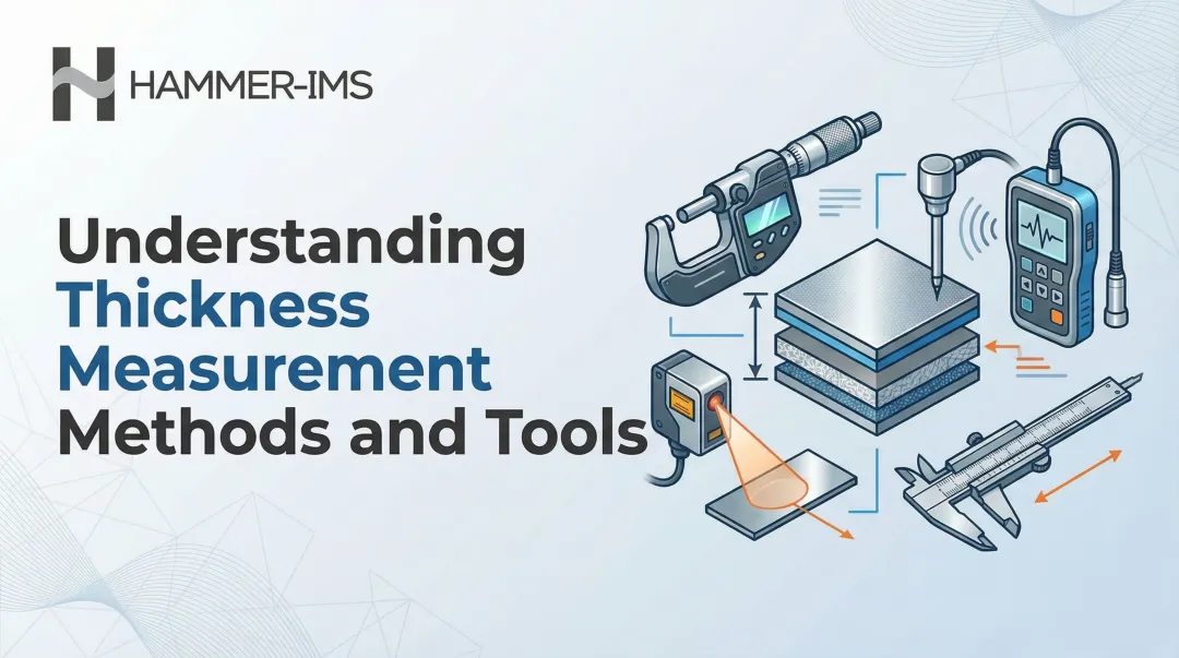
Thickness Measurement Techniques Used in Calendering
Several distinct measurement technologies are used depending on material type, production speed, surface characteristics, and required precision. Understanding the working principle of each helps teams select and deploy the right tool for their specific application.
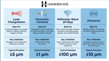
Laser Triangulation
Operating Principle:
Laser triangulation projects a laser beam onto the material surface and uses the reflected angle to calculate distance. Thickness is derived by comparing top and bottom sensor readings, or by measuring distance from the sensor to the material surface against a calibrated roller reference. This technique is widely used in rubber and film calendering due to its non-contact nature and relatively straightforward implementation.
Limitations and Challenges:
Laser triangulation struggles with diffused reflections from shiny or dark surfaces. Black rubber, in particular, absorbs laser light rather than reflecting it cleanly, producing noisy or erroneous readings. IR lasers operating at 808 nm wavelength partially address reflectivity issues for rubber applications.
These sensors are also susceptible to angle drift and face challenges maintaining accuracy on vibrating or oscillating calender frames, where positional noise must be compensated through mounting design and signal filtering.
Chromatic Confocal Sensors
Operating Principle:
Chromatic confocal technology uses a white light source focused onto the material surface. Different wavelengths focus at different distances due to chromatic aberration in the optical path. Reflected light is analyzed through a spectrometer, which determines surface position based on the wavelength that reflects most strongly. This approach makes the technology insensitive to surface reflectivity variations, colour changes, and roughness differences.
Precision Applications:
Chromatic confocal sensors excel in high-precision applications. Modern battery electrode calenders achieve gap accuracies of ±1 µm under massive compression forces (up to 300 tons) and temperatures up to 200°C, often using chromatic confocal measurement to verify thickness. Repeatability under 0.5 microns makes this technology the current benchmark for ultra-precision calendering where even fractional micron deviations are unacceptable.
Millimeter Wave (M-Ray) Technology
Operating Principle:
Millimeter wave-based measurement operates at 60 GHz, using electromagnetic waves that penetrate material layers. The technology measures the time it takes for waves to traverse through materials—electromagnetic waves slow down when penetrating substances like rubber, plastics, and nonwovens. Through accurate time measurements of this propagation delay, the system calculates both thickness and basis weight.
Material Versatility:
Unlike optical technologies, M-Ray performance is independent of surface colour, shine, or texture. This makes it highly versatile across rubber, nonwovens, foams, and multi-layer composites where laser reflection is unreliable.
Hammer-IMS's M-Ray technology offers contactless measurement with real-time feedback capability and integration into closed-loop calender control systems—enabling active process adjustment rather than passive data logging. The technology maintains 1 gsm measurement accuracy even at high stand-off distances, making it a practical alternative to nuclear gauging without the associated regulatory burden.
Calender-Specific Deployment:
M-Ray systems support multiple mounting configurations including fixed or travelling sensors for maximum cross-machine direction coverage. The technology operates at measurement rates of 3 kHz, allowing production lines to reach speeds up to 500 m/min whilst maintaining continuous thickness monitoring across the full web width.
Ultrasonic Measurement
Operating Principle:
Ultrasonic gauging measures the time-of-flight of sound waves through the material. A transducer emits ultrasonic pulses that travel through the material and reflect back from the opposite surface. The round-trip time, combined with the known speed of sound through that material, determines thickness.
Best-Fit Applications:
This technique is well-suited for soft, porous, or compressible materials where laser reflection is unreliable—such as foams, nonwovens, and certain rubber compounds. Coupling agents (gels or liquids) may be required to ensure acoustic contact, though air-coupled ultrasonic variants exist. Production-line integration can be more complex compared to optical or electromagnetic methods due to coupling requirements and sensitivity to material density variations.
Technology Comparison at a Glance
| Technology | Best For | Key Limitation | Typical Precision |
|---|---|---|---|
| Laser Triangulation | Rubber, film | Poor on dark/shiny surfaces | Low–medium |
| Chromatic Confocal | Battery electrodes, ultra-thin film | High cost, limited material range | ±0.5 µm |
| Millimeter Wave (M-Ray) | Rubber, nonwovens, foams, composites | Requires material-specific calibration | 1 gsm basis weight |
| Ultrasonic | Foams, soft nonwovens | Coupling agents often needed | Medium |
Key Challenges in Calendering Thickness Measurement
Surface and Material Variability
Shiny, dark, or wet surfaces—common in rubber and coated film calendering—cause reflection-based sensors to produce noisy or erroneous readings. Black rubber absorbs laser energy rather than reflecting it cleanly. Wet surfaces from cooling or coating processes create specular reflections that confuse triangulation algorithms. A documented case notes how previous laser-based solutions failed to handle variations in sheet colour and transparency, while M-Ray technology successfully measured across all material conditions.
Compressible or fibrous materials — nonwovens and textiles in particular — behave differently under sensor conditions than under calender pressure. Once tension releases, the material recovers elastically, meaning post-calender readings can differ from final product thickness.
Measurement systems must account for this "springback" effect to correlate in-process data with final product specifications.
High-Speed Production and Vibration
Calender lines often run at speeds up to 1000 m/min, where measurement systems must deliver rapid, continuous readings without lag. At these speeds, a 100-millisecond response delay translates to over 1.5 metres of unmeasured material—enough to miss localized defects entirely.
Mechanical vibration from rotating rolls, thermal expansion of calender frames, and oscillating web tension introduce positional noise that sensors interpret as thickness variation. Mechanical frames holding thickness sensors are highly susceptible to thermal expansion; a 25°C ambient temperature change can cause an uncompensated frame to shift, creating a perceived thickness error of almost 400 microns. Systems designed for these environments typically address this through:
- Vibration-dampened mounting to isolate sensor movement from roll vibration
- Invar material frames that minimize thermal expansion across temperature shifts
- Capacitive sensors that continuously monitor and compensate for frame geometry changes
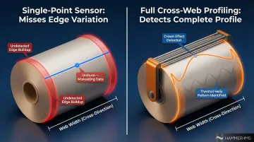
Single-Point vs. Cross-Web Coverage
A single fixed sensor gives only a centreline reading and completely misses edge-to-edge thickness variation. Roll separating forces cause rolls to bow apart at the centre, creating "crown effect" where material is thinner in the middle and thicker at the edges. Thermal gradients can create even more complex patterns—a documented 1989 study found a "thermal helix" pattern with 2.2 turns across an 8.25-metre web, causing thickness to range from 63 to 93 µm.
Full cross-web profiling catches what single-point measurement misses entirely. Traversing sensors (C-frame or O-frame designs) and fixed multi-sensor arrays each serve this purpose by:
- Capturing the complete thickness profile across the web width
- Detecting calender roll deflection, thermal distortion, and edge variation
- Allowing operators to separate global thickness drift from localized defects requiring different corrective actions
Tips to Improve Thickness Measurement Accuracy on Calender Lines
Use Cross-Web Profiling for Complete Coverage
Rather than relying on a single measurement point, deploy traversing sensors or fixed multi-sensor arrays. C-frame and O-frame scanners move across the entire working width, capturing full cross-web thickness profiles. Some O-frame systems accommodate up to five sensors simultaneously, scanning widths up to 6.6 metres at machine speeds up to 2000 m/min.
Why it matters: Cross-web profiling detects roll crown, taper, thermal helix patterns, and edge buildup that single centreline sensors miss. This data enables precise diagnosis—distinguishing between problems requiring roll grinding, thermal compensation, or gap adjustment.
Establish Rigorous Calibration Routines
Sensors should be zeroed against a known reference (bare roller surface or certified gauge block) at the start of each production run and after any roll change or temperature shift. Document calibration intervals and flag drift trends before they translate into product defects.
Advanced systems include automated in-situ calibration, periodically returning to a calibration position to measure certified standards and readjust values for mechanical frame changes. This automation removes human error and ensures measurement integrity across multiple shifts.
Decouple Sensors from Mechanical Vibration
Mount measurement frames independently of the calender structure where possible. Use vibration dampening and apply signal averaging or filtering in the acquisition software to distinguish real thickness variation from mechanical noise. This is especially important on older calender frames where structural vibrations are more pronounced.
Modern systems use patented compensation frames made from Invar material combined with capacitive sensors that continuously monitor and compensate for changing gaps between top and bottom frames, as detailed by CMM Magazine. Mounting sensor heads on separate, vibration-stabilized machine frames decoupled from calendering rollers minimises the influence of web vibrations on measurement accuracy.
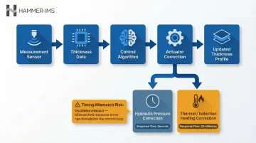
Integrate Measurement Data into Closed-Loop Control
Thickness data that only generates a report after the fact has limited value. Connecting the measurement system to roll gap actuators or nip pressure controls enables real-time closed-loop correction, reducing thickness drift without operator intervention.
According to TAPPI research, caliper corrections of approximately ±1 µm are attainable in soft-nip calendering with ±50 N/mm of nip force adjustment.
Zonal deflection-controlled rolls address broad-wave irregularities, while induction heating units handle narrow-wave corrections in 38–76 mm zones. These heating units generate localised temperature differences of 10–25°C to modify roll diameter and correct thickness profiles in real time.
Critical consideration: Different actuators have vastly different response times. Hydraulic pressure corrections take seconds, whilst thermal devices may require over 20 minutes to become fully effective. Control algorithms must account for these timing differences to avoid oscillation and instability.
Account for Springback and Material Behaviour
For elastic or compressible materials (foams, nonwovens, some rubbers), thickness measured immediately post-calender may differ from final product thickness once tension is released. Understand whether your measurement point captures in-nip thickness or recovered value, and calibrate acceptance criteria accordingly.
Some materials exhibit time-dependent recovery, meaning thickness continues changing for seconds or minutes after leaving the nip.
In these applications, measurement positioning becomes critical: too close to the nip captures compressed thickness; too far captures fully recovered thickness. Match measurement location to customer specifications and end-use requirements.
Choosing the Right Thickness Measurement System for Your Calender Line
Match Technology to Material Characteristics
For highly reflective or dark-surface materials (rubber, coated films), avoid standard laser triangulation without IR compensation or alternative technologies. Black rubber requires either IR lasers at 808 nm wavelength or non-optical measurement methods entirely.
For multi-layer or opaque composites, consider technologies that measure total thickness independent of individual layer reflectivity. M-Ray technology, for example, penetrates material layers and measures combined thickness without sensitivity to colour or transparency variations in individual plies.
For ultra-precision applications (battery electrodes, optical films), prioritize systems offering sub-micron repeatability. Chromatic confocal technology currently leads this category, though advanced M-Ray implementations also achieve high precision without surface reflectivity constraints.
Consider Production Environment Requirements
Calender environments often involve heat, steam, dust, or solvent vapours. Ensure the chosen system carries appropriate IP ratings and that sensor optics or electronics are protected through enclosures or purge air systems.
Nuclear gauges, while still in use, face increasing regulatory and safety pressure in many markets. European regulatory frameworks increasingly restrict nuclear technology use, with agencies evaluating new nuclear installations against non-nuclear alternatives. If non-nuclear technologies perform similarly or better, regulatory bodies may deny nuclear licences entirely.
Non-nuclear alternatives like M-Ray eliminate licensing requirements, specialised safety protocols, and source replacement costs while maintaining measurement accuracy.
Evaluate Integration and Data Output Capabilities
A measurement system that delivers only a local display has limited operational value. Look for systems with open data interfaces supporting:
- OPC-UA for real-time data exchange with third-party PLC systems
- Modbus TCP/IP for direct hardware and software integration
- PROFINET for industrial networking
- Analog outputs for legacy control systems
Data logging, remote connectivity, and MES/SCADA integration support trend analysis, audit trails, and continuous improvement initiatives.
Hammer-IMS's Connectivity 3.0 software extends these capabilities further — built-in calibration algorithms, native connectivity with Beckhoff and Siemens PLCs, and direct reporting to SQL databases or FTP servers with optional Grafana dashboards for historical analysis.
Research Total Cost of Ownership
Include not just purchase price but:
- Calibration consumables: Certified gauge blocks, reference standards
- Source replacement: For nuclear gauges, radioactive source replacement every 5–10 years represents significant cost and regulatory burden
- Maintenance downtime: Complexity of sensor servicing and availability of spare parts
- Software licensing: Ongoing fees for updates, remote connectivity, and advanced features
- Regulatory compliance: Licensing fees, safety training, and documentation requirements for nuclear systems
Non-contact, source-free systems typically offer lower long-term operational costs and simpler compliance management. Removing radioactive sources from the equation eliminates specialised safety protocols, protective measures, and dedicated training programmes — reducing both overhead and administrative burden over the system's lifetime.
Frequently Asked Questions
What measurement is used for thickness?
Several measurement methods are used depending on application: laser triangulation, chromatic confocal, millimeter wave (M-Ray), and ultrasonic technologies are the most common for industrial thickness gauging. The best choice depends on material properties (colour, reflectivity, compressibility) and required precision.
What is the most accurate method for measuring thickness in calendering?
Chromatic confocal technology offers the highest precision, with sub-0.5 micron repeatability, and is widely used in battery electrode calendering. Millimeter wave systems offer excellent accuracy for a broader range of materials without sensitivity to surface colour or reflectivity, making them versatile across rubber, nonwovens, and composites.
Can thickness be measured without contacting the material?
Non-contact measurement is the standard approach for most calender lines. Laser triangulation, chromatic confocal, and millimeter wave technologies all operate without touching the web—avoiding marking, deformation, or contamination of the product whilst enabling measurement at high production speeds.
How does in-line thickness measurement improve calendering efficiency?
Continuous in-line data enables real-time closed-loop control of roll gap or nip pressure, reducing thickness variation, cutting raw material overuse, and minimising rejected product. Unlike offline spot checks, which catch defects only after material has been produced, in-line measurement allows immediate process correction before waste accumulates.
What causes thickness variation in the calendering process?
Main sources include thermal expansion of calender rolls, roll deflection under load (crown effect), inconsistent material feed, and wear over time. Continuous measurement systems detect these patterns and enable real-time process correction before they affect product quality.
What industries rely most on calendering thickness measurement?
Key sectors include tyre and rubber manufacturing, battery electrode production, plastic film and sheet extrusion, nonwovens, technical textiles, and construction materials. Each relies on tight thickness tolerances to meet performance specifications and control material costs.