Introduction
Surface defects in continuous production aren't just quality issues—they're financial liabilities. A scratch missed during extrusion, a thickness deviation undetected in a nonwoven line, or a contamination spot on a plastic film can cascade into warranty claims, rejected shipments, and production downtime that costs thousands per hour. Industry data shows that defects caught inline cost orders of magnitude less than those caught downstream, yet many manufacturers still rely on periodic sampling or inconsistent human inspection.
Machine vision surface inspection systems solve this problem by automating defect detection using sensors, imaging technology, and processing algorithms to verify material quality in real time, without human intervention.
This article is written for quality engineers, plant managers, and process control teams in industries where surface quality ties to product performance: textiles, nonwovens, plastics, automotive, and electronics. What follows covers what these systems are, how they work, where they're applied, and where their limits lie.
Key Takeaways
- Machine vision surface inspection systems use cameras, sensors, and algorithms to detect defects and flag anomalies in production—faster and more consistently than human inspectors
- Applied across textiles, nonwovens, plastics, automotive, and electronics where surface quality affects end-product performance
- Captured surface data is processed against programmed criteria to output pass/fail decisions or real-time feedback to production controls
- Performance depends on sensor technology, lighting, material properties, line speed, and production system integration
- Not universally appropriate; some materials, defect profiles, or environments require specialised or complementary approaches beyond standard optical systems
What Is a Machine Vision Surface Inspection System?
A machine vision surface inspection system is an automated quality control technology that captures data from a product or material surface, processes it using algorithms or AI, and determines whether the surface meets defined quality criteria—all without stopping the production line. These systems deliver consistent, objective detection of surface anomalies at production speeds that manual inspection cannot match, including:
- Scratches and voids
- Contamination and foreign particles
- Pattern irregularities
- Thickness deviations
How It Differs from General Machine Vision
General machine vision covers dimensional measurement, barcode reading, and robot guidance. Surface inspection is a distinct discipline: it focuses on detecting and characterizing anomalies across the full material surface—often across wide, continuous webs or sheets rather than individual discrete parts. Where standard machine vision verifies a static part, surface inspection must handle full-width scanning of materials moving at line speed.
Why Surface Inspection Matters in Industrial Manufacturing
Surface defects in materials like films, nonwovens, textiles, foam, and metal sheet often don't manifest as visible failures until they reach end-use, triggering costly recalls, warranty claims, or rejection by downstream processors. Structural defects and processing limitations in polymer film applications alone represent yield loss drivers, with late-stage defect detection costing 10-100 times more than inline detection.
Manufacturing demands addressed by surface inspection:
- Uniform material properties across full width and length
- Tight tolerances on thickness or basis weight
- Absence of surface contamination or voids
- Traceability of quality data per production batch
Without inline inspection, those demands go unmet in predictable ways:
Common failure modes without real-time inspection:
- Periodic offline sampling misses defects between sample points
- Human visual checks are inconsistent on lines running hundreds of meters per minute
- Production runs cannot self-correct before significant waste accumulates
- Entire batches get scrapped, driving customer complaints and margin erosion
How Machine Vision Surface Inspection Systems Work
A machine vision surface inspection system acquires surface data as material moves through the inspection zone, then processes that data against stored quality criteria to generate a decision or measurement output. In advanced installations, that output feeds directly back into the production process, enabling closed-loop adjustment in real time.
Sensing and Image Acquisition
The system uses sensors or cameras—optical line-scan cameras, area-scan cameras, or non-optical scanning technologies such as millimeter-wave sensors—to capture surface data across the full width of the material. For optical systems, lighting design critically affects image contrast and defect visibility:
- Backlighting reveals pinholes and voids by transmitting light through the material
- Coaxial lighting highlights surface scratches and texture variations
- Darkfield illumination amplifies surface irregularities by reflecting light at low angles
Non-optical systems like Hammer-IMS's M-Ray millimeter-wave technology measure thickness and basis weight by transmitting electromagnetic waves through the material, capturing reflected signals to determine material properties without reliance on visual contrast.
Processing and Analysis
Captured data is passed to a processing unit running inspection algorithms:
- Rule-based logic flags deviations from defined parameters, such as size thresholds or grayscale values
- AI and deep learning models identify complex or variable defect types that rules alone cannot reliably classify
- Hybrid configurations combine both approaches, using rules for known defect types and AI for anomaly detection

The system compares each frame or scan line against a reference or tolerance model in real time. For continuous webs, this happens hundreds of times per second as material flows through the inspection zone.
Output and Control
The system outputs its findings in three primary ways:
- Pass/fail signal to a rejection or marking mechanism
- Measurement value fed to a data log for traceability
- Adjustment signal sent directly to production equipment — for example, adjusting die gap, tension, or coating weight — to keep the process within specification
When a system can act on its findings rather than only record them, inline inspection becomes a process control tool — not just a quality gate. Hammer-IMS's Connectivity 3.0 platform supports this by enabling real-time production adjustment and integrated data logging across manufacturing lines.
Where Machine Vision Surface Inspection Systems Are Applied
Material Types and Industry Sectors
Surface inspection covers three broad material categories, each with distinct technical requirements:
- Continuous web materials (nonwovens, textiles, plastic film and sheet, paper, foam, rubber) — require full-width inline scanning to catch defects across the entire production width
- Discrete parts (metal stamped components, molded plastics, glass panels) — use area-scan or structured light inspection for each individual component
- Surface coatings and laminates — require uniformity checks and layer integrity verification to confirm consistent coverage
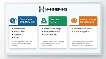
For nonwovens, technical textiles, and plastic film production — the sectors Hammer-IMS serves — inline surface inspection is especially critical for controlling thickness uniformity and basis weight variation across the full web width.
Points in the Production Lifecycle
Inspection can occur at multiple stages depending on production type:
- Inline during continuous production (most common and highest-value)
- Roll change or cut-to-length points
- Converting or laminating steps
- Final QA before shipment
For continuous web production, inspection runs 100% inline without interruption. For discrete parts, coverage may be every-part or statistical depending on risk tolerance. Maintenance and compliance applications sometimes add periodic offline inspection to supplement the inline data.
Key Factors That Affect System Performance
Material Properties Influence System Design
Highly reflective, transparent, or textured surfaces behave differently under optical illumination and may require specialized lighting geometries, multiple sensor angles, or non-optical sensing to reliably detect surface defects. Standard machine vision approaches struggle with materials like shiny metallized films or open-structure nonwovens, where optical contrast is insufficient.
Line Speed and Resolution Trade-Offs
Faster production lines demand higher sensor acquisition rates and faster processing pipelines. Maintaining detection sensitivity at higher speeds often requires more sophisticated — and more expensive — hardware.
The relationship between spatial resolution, web speed, and defect detectability is direct: faster lines reduce the time available to capture and process each frame, raising the minimum detectable defect size unless processing power scales to match.
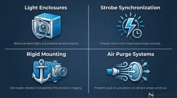
Lighting Conditions and Installation Environment
Ambient light interference, vibration, dust, and temperature fluctuations in industrial environments can all degrade image quality. Engineering controls for these conditions include:
- Enclosures to block ambient light and protect optics
- Strobe synchronization to freeze motion and improve contrast
- Rigid mounting to eliminate vibration-induced blur
- Air purge systems to prevent dust accumulation on sensor windows
Software, Algorithms, and Training Data
Rule-based systems execute quickly and predictably, but struggle when defect appearances vary. AI and deep learning systems handle that variability well — provided they're trained on sufficient representative data and validated continuously to stay accurate. False positive rates in industrial surface inspection can significantly impact operational efficiency, making algorithm tuning and validation essential.
Integration with Production Systems
A surface inspection system that outputs data to a dashboard but cannot trigger process adjustments only provides reactive quality control. Systems integrated with PLCs, MES, or process controllers enable proactive correction — the higher-value deployment model.
Hammer-IMS's Connectivity 3.0 platform supports this closed-loop model through integrations including:
- Profinet and TCP/IP connectivity to production equipment
- Real-time feedback to die adjustment systems
- Automated correction of coating controls and line speed regulators
Common Misconceptions and When the System May Not Be Appropriate
Misconception: Any Camera-Based System Can Inspect Any Surface
In reality, optical systems designed for discrete parts (screws, PCBs) are not engineered for continuous wide-web materials, and vice versa. Selecting the wrong system architecture leads to persistent false positives, missed defects, or unacceptably high reject rates.
Situations Where Standard Optical Vision Is Limited
Several material and process conditions push optical vision beyond its practical limits:
- Translucent or transparent materials where surface features don't generate sufficient optical contrast — non-optical sensing is typically required
- Surfaces with high natural variability, such as woven textiles, where distinguishing real defects from acceptable texture demands multi-modal or non-optical approaches
- High-speed lines where acquisition rates can't match throughput, leaving gaps in coverage
When Machine Vision Is Used by Default Rather Than Need
In applications where defect rates are extremely low and defects are non-critical, the cost and complexity of a full inline inspection system may not be justified. Periodic offline sampling or simpler gauging solutions may deliver adequate quality assurance at lower investment. Teams should evaluate inspection requirements against actual defect risk and downstream consequences before specifying a system.
Frequently Asked Questions
What is the difference between surface inspection and dimensional inspection in machine vision?
Surface inspection detects anomalies across the material surface — scratches, voids, stains, and pattern defects. Dimensional inspection measures geometric features like length, width, thickness, and tolerances. Advanced systems often combine both, but each requires different sensor configurations and algorithms.
What types of defects can machine vision surface inspection systems detect?
Common defect categories include visual defects (scratches, pinholes, contamination, colour variation), structural defects (voids, delamination, thickness variation), and pattern defects (weave irregularities, print misalignment). Detectability depends on defect size relative to system resolution and the contrast generated by the chosen sensing method.
How fast can machine vision surface inspection systems operate?
Modern inline systems can inspect materials moving at several hundred metres per minute for continuous web production. Actual throughput depends on line scan camera speed, lighting strobe frequency, and processing hardware. System specs must match maximum line speed to avoid gaps in coverage.
Can machine vision surface inspection systems be retrofitted to existing production lines?
Most systems are designed for inline integration and can be installed on existing lines with appropriate mounting structures. Integration complexity depends on whether detection alone is needed or whether closed-loop feedback to production controls is also required.
What is the difference between optical and non-optical surface inspection systems?
Optical systems use cameras and light to detect surface anomalies visually. Non-optical systems — such as millimetre-wave or ultrasonic scanning — interact with or penetrate the material to detect sub-surface properties like thickness or density. Non-optical methods are preferred when optical contrast is insufficient, such as with translucent or reflective materials.