Introduction
Modern manufacturing can no longer rely solely on manual inspection—production speeds, complexity, and quality demands have outpaced what human inspectors can reliably catch. The stakes are high: missed defects mean costly recalls, extensive rework, wasted material, and lost revenue. According to the American Society for Quality, Cost of Poor Quality (COPQ) typically consumes 15% to 20% of total sales revenue for average manufacturers, with some organizations seeing this figure climb to 40% of total operations costs.
Compounding this challenge, manufacturers face persistent labor shortages. The National Association of Manufacturers reports that approximately 4.2% of manufacturing positions remain unfilled, with one in four manufacturers experiencing vacancy rates above 5%.
These twin pressures—quality risk and workforce gaps—are pushing manufacturers across textiles, plastics, automotive, and other industries toward machine vision inspection systems that can catch defects automatically, at line speed, without fatigue.
This guide answers the key questions: what these systems are, how they work, what components they require, and what to look for when evaluating one for your production line.
Key Takeaways
- Machine vision inspection systems combine cameras, lighting, and software to automate quality control on production lines
- They capture and analyze images in real time to detect defects, verify dimensions, and trigger process adjustments
- Core components include sensors/cameras, lighting, lenses, a processing unit, and inspection software
- Inline inspection delivers 100% coverage, consistent accuracy, faster throughput, and less waste
- Specialized non-contact technologies — such as millimeter-wave systems — extend quality control to continuous materials like textiles, films, and nonwovens
What Is a Machine Vision Inspection System?
Machine vision inspection is a technology that uses industrial cameras, controlled lighting, and computer vision software to automate the detection of product defects, dimensional errors, and quality deviations on manufacturing lines—without human visual inspection. These systems replace or augment manual inspection processes that are inherently limited by human fatigue, inconsistency, and throughput constraints.
The core purpose is straightforward: enable 100% product coverage at full production speed, 24/7, with no fatigue or accuracy degradation. Unlike sampling-based spot checks that leave quality gaps, machine vision systems inspect every single unit or every continuous meter of material passing through the line.
Understanding what these systems do today means tracing how inspection technology got here.
Evolution of Inspection Technology
The shift from manual inspection to today's AI-enabled systems happened in three distinct phases:
- Manual inspection: Human inspectors checking products visually, limited by fatigue and inconsistency
- Rule-based machine vision: Computer systems using fixed thresholds and template matching to detect known, predefined defects
- AI-enabled systems: Deep learning algorithms trained on labeled defect examples, capable of detecting anomalies invisible to the human eye and adapting as new defect types emerge
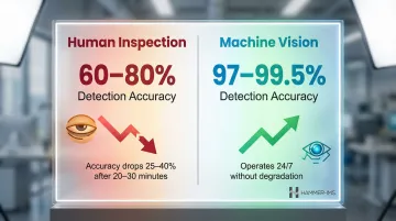
Research shows the dramatic difference: human inspectors catch only 60-80% of defects, with accuracy dropping 25-40% after the first 20-30 minutes of repetitive tasks. In contrast, computer vision systems achieve 97-99.5% detection accuracy operating continuously.
Discrete Parts vs. Continuous Material Inspection
Two distinct inspection architectures serve different manufacturing needs:
| Architecture | Camera Type | Best For |
|---|---|---|
| Discrete Parts Inspection | Area scan cameras — capture complete images of individual components or assemblies | Packaged goods, machined parts, assemblies moving on conveyors |
| Continuous Web Inspection | Line scan cameras — capture one pixel line at a time as material passes the sensor | Textiles, plastic film, nonwovens, paper, steel strip — materials that never stop moving |
For web-based manufacturers in particular, line scan architecture is the only viable option: production runs continuously and material widths exceed what any single area scan frame can capture.
Core Manufacturing Challenges Addressed
Machine vision inspection systems solve five critical manufacturing challenges:
- Tighter tolerances and more inspection points as product complexity increases
- Fewer available skilled quality inspectors due to persistent labor shortages
- Inconsistency caused by human fatigue and subjectivity during repetitive tasks
- Production speeds that outpace what any manual process can reliably inspect
- Regulatory and traceability requirements demanding documented proof of 100% inspection coverage
Core Components of a Machine Vision Inspection System
Every machine vision inspection system consists of hardware components (the "eyes and body") and software (the "brain"). The right configuration depends entirely on the application—product type, line speed, defect characteristics, and environment.
Cameras and Sensors
Industrial cameras serve as the primary image capture component. Two main types dominate:
Area Scan Cameras capture a full 2D image in a single exposure using a rectangular sensor array. They're ideal for stationary objects, discrete parts, and standard production lines where objects fit within a single frame. Key selection criteria include:
- Resolution — ranging from VGA to high-megapixel sensors (21 MP and above)
- Frame rate — determines inspection speed capability
- Color vs. monochrome — color adds information but reduces sensitivity
- Sensor type — CMOS offers speed and flexibility; CCD provides superior image uniformity
Line Scan Cameras capture images one line of pixels at a time, stitching them together to create continuous images. They're mandatory for continuous web manufacturing. Available in resolutions from 2k to 32k pixels per line with speeds reaching 1 MHz (16 Gigapixels/second), these cameras handle unlimited image lengths without geometric distortion.
Lighting Systems
Controlled lighting is critical—ambient factory light is inconsistent and unpredictable. Purpose-built lighting enhances contrast and reveals defects the camera would otherwise miss.
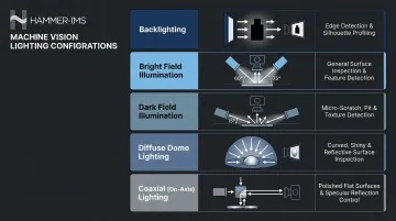
Common configurations include:
| Lighting Type | Application | Best For |
|---|---|---|
| Backlighting | Creates dark silhouette with maximum contrast | Dimensional measurements, edge detection, hole verification |
| Bright Field | Light directed from above at 45°-90° | General surface inspection, highlighting topography |
| Dark Field | Low-angle light (0°-45° off horizontal) | Micro-defects like scratches, pits, engravings |
| Diffuse Dome | Hemispherical multi-directional illumination | Curved, shiny, or uneven specular surfaces |
| Coaxial | Light aligned with camera's optical axis | Highly reflective flat surfaces (wafers, polished metal, glass) |
The lighting geometry dictates defect visibility. Specular (shiny) surfaces require diffuse dome or coaxial lighting to prevent glare, while dark field lighting reveals microscopic surface scratches.
Optics and Lenses
The lens determines field of view, working distance, and measurement precision. Key considerations include:
- Focal length selection — balancing magnification and working distance
- Telecentric lenses — eliminate perspective distortion for dimensional accuracy, essential for high-precision metrology where magnification must remain constant regardless of object distance
- Protective filters — safeguarding optics in harsh environments
High-quality telecentric lenses exhibit extremely low geometric distortion, typically below 0.1%, making them essential for applications requiring true object size measurements.
Processing Hardware and Software
The processing unit—industrial PC, embedded controller, or smart camera—receives the image and runs inspection algorithms. Two main software approaches exist, each suited to different inspection challenges:
| Approach | How It Works | Best For |
|---|---|---|
| Rule-Based | Thresholding, template matching, deterministic algorithms | Well-defined defects in controlled, consistent environments |
| AI / Deep Learning | Trains on labeled examples, adapts to variation | Complex or variable defects, anomalies rule-based logic would miss |
The human-machine interface (HMI) lets operators monitor system status and review results in real time. Output signals—pass/fail decisions, defect logs, and trend data—feed directly into PLCs, MES, or analytics platforms, giving production teams the visibility needed to act before defects compound.
How Machine Vision Inspection Systems Work
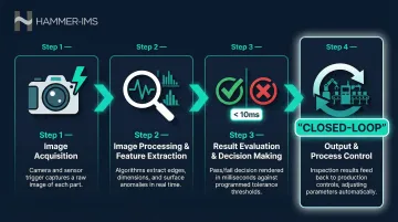
The inspection sequence is a repeatable, high-speed loop that occurs for every product or material section passing through the system.
Step 1 — Image Acquisition
A proximity sensor or encoder triggers the camera at the precise moment a part or material section enters the field of view. Lighting activates simultaneously to ensure consistent illumination. For continuous web applications (textiles, films), encoders synchronize image capture with conveyor speed rather than discrete part triggers, maintaining precise pixel-to-distance calibration.
Step 2 — Image Processing and Feature Extraction
The acquired image undergoes preprocessing — noise reduction, contrast enhancement, edge detection — before algorithms extract features relevant to the application. Common targets include:
- Surface texture and finish anomalies
- Dimensional measurements and geometry
- Label text and barcode readability
- Seal integrity and closure quality
Advanced systems run multiple processing techniques in parallel to evaluate several quality attributes from a single image capture.
Step 3 — Result Evaluation and Decision Making
Extracted data is compared against predefined tolerances or trained defect models. The system classifies each inspected unit or section as pass or fail, or assigns a defect category and severity. This decision occurs in milliseconds, keeping pace with production.
Step 4 — Output and Process Control
The downstream actions vary by sophistication:
- Basic systems send rejection signals to sorting gates or alarms to operators
- Advanced closed-loop systems provide direct feedback to production machines to adjust process parameters (die gap, tension, coating weight) in real time
This closed-loop capability transforms machine vision from a passive detector into an active production optimizer. In continuous material production lines, for instance, Hammer-IMS's Connectivity 3.0 software feeds measurement data directly back into the process — enabling the system to automatically adjust bolt power, line speed, and pump flow control through PI controller systems to maintain correct thickness profiles.
Types of Machine Vision Inspection Systems in Manufacturing
Manufacturers choose from three main system architectures:
| Architecture | Best For | Trade-offs |
|---|---|---|
| Smart Camera Systems | Single-point inspections — barcode reading, presence/absence verification | Limited processing power; restricted to well-defined tasks |
| PC-Based Systems | High-speed, multi-camera web inspection, line scan, complex metrology | Higher cost and larger footprint; required for sophisticated algorithms |
| Embedded/Vision Appliance Systems | Multi-camera setups in harsh environments, mid-complexity applications | Middle ground — no full PC overhead, but less flexible than PC-based |
Camera-Based vs. Non-Contact Measurement Technologies
Visible-light cameras handle surface defects well, but continuous material producers often need to measure properties no camera can see — basis weight, moisture content, coating thickness. That's where non-contact measurement technologies come in:
| Technology | Measurement Principle | Range/Precision | Ideal Materials |
|------------|----------------------|-----------------|-----------------|
| Millimeter-Wave (M-Ray) | Time-of-flight/attenuation of electromagnetic waves (radiation-free) | Up to 10,000 gsm; precision of 1 gsm | Nonwovens, coated textiles, plastic films, synthetic foams |
| Near-Infrared (NIR) | Absorption of specific IR wavelengths by organic molecular bonds | 2 µm to 5 mm; accuracy approx. 0.05 g/m² for coatings | Polymer films, aqueous/dry coatings, moisture content, battery separators |
| X-Ray (Non-Nuclear) | X-ray absorption using digitally tuned, low-power source (10-30 keV) | 20 to 58,000 g/m²; repeatability of ±0.025% | Steel strip, fiberglass, float glass, heavy nonwovens |
These technologies replace legacy nuclear (Beta/Gamma) gauges, eliminating radioactive source disposal costs and safety hazards while providing high-resolution cross-directional profiling.
Choosing the right system comes down to four variables:
- Material type — discrete parts or continuous web
- Line speed — how fast the production process runs
- Defect type — surface visual defects vs. dimensional or physical properties
- Integration depth — how tightly the system needs to connect with production controls
Key Benefits and Business Impact
Machine vision systems deliver 100% inline inspection coverage at full production speed, eliminating sampling error. Computer vision systems achieve 97–99.5% detection accuracy, compared to 60–80% for manual inspection, while operating 24/7 without degradation. Automated rejection or real-time feedback then reduces downstream rework and scrap.
Production efficiency gains stem from real-time data visibility. Manufacturers identify process drift early, reduce material overuse by maintaining tighter thickness margins, and improve overall equipment effectiveness (OEE). This is especially relevant for continuous material producers where even small thickness variations across a wide web translate into significant material waste. For example, a steel manufacturing case study showed AI vision reduced customer quality complaints by 65% and increased defect detection accuracy from 72% to 98.5%.
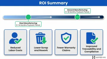
The financial case is equally strong. In steel manufacturing, CMMS-integrated AI vision inspection yields a typical payback period of 8 to 14 months, while general manufacturing typically sees returns within 6 to 18 months. Key cost drivers include:
- Reduced labor costs from automated inspection replacing manual checks
- Lower scrap and rework through early defect detection
- Fewer warranty claims and customer complaints
- Improved traceability supporting regulatory compliance
Implementing a Machine Vision Inspection System: Key Considerations
Manufacturers should define several planning essentials before selecting a system:
- Inspection objectives: Define which defect types or parameters need detection — surface scratches, dimensional tolerances, color variations, or internal material properties — as this determines sensor technology and algorithm requirements.
- Production line constraints: Account for line speed, environmental conditions (temperature, vibration, dust), and available mounting space, since these dictate hardware ruggedization and mounting architecture.
- Integration requirements: Confirm PLC, MES, or ERP compatibility. Modern systems support industrial protocols including EtherNet/IP, PROFINET, Modbus TCP, and OPC UA for direct integration with existing plant infrastructure.
- Material handling mode: Whether you're inspecting discrete parts or continuous material drives fundamental architecture choices — area scan vs. line scan cameras, triggering mechanisms, and software logic.
With these parameters established, the focus shifts to validating the system before production goes live.
Validation and Deployment
Before go-live, test the system against representative samples of both known-good and known-defect products. Establish baseline performance metrics — detection rate and false positive rate — and train operators on HMI use and alert response protocols.
In regulated environments (automotive, pharmaceutical), validation must follow the IQ/OQ/PQ protocol:
- Installation Qualification (IQ) — Verify hardware and software are installed to manufacturer specifications
- Operational Qualification (OQ) — Test against controlled test samples
- Performance Qualification (PQ) — Run under actual production conditions for statistically significant sample size
AI-based systems require labeled training data to be built before deployment, which can extend implementation timelines but delivers superior defect detection for complex or variable applications.
Long-Term Maintenance
System performance should be monitored continuously using logged inspection data to catch any drift in detection accuracy. Regular maintenance includes:
- Calibration to account for lighting degradation or lens drift
- Software updates for model performance improvements
- Spare parts and support plan to minimize downtime
Advanced systems like Hammer-IMS's Connectivity 3.0 platform enable remote monitoring and support, allowing technical teams to diagnose issues and adjust parameters without on-site visits.
Frequently Asked Questions
What is the difference between machine vision inspection and traditional quality control?
Traditional QC relies on manual or sampling-based inspection, which is subject to human fatigue and limited throughput. Machine vision systems inspect 100% of products automatically at production speed with consistent accuracy, eliminating sampling gaps and human variability.
What industries benefit most from machine vision inspection systems?
Key sectors include automotive, electronics, food and beverage, pharmaceuticals, packaging, textiles, nonwovens, and plastic film production. What these sectors share is high output volume, tightly defined quality standards, and the need to reduce dependence on manual inspection labor.
How accurate are machine vision inspection systems compared to human inspectors?
Machine vision systems outperform human inspectors on consistency, particularly at high speeds where attention degrades. Well-configured systems maintain 97–99.5% detection rates, though results depend on lighting quality, calibration, and algorithm design.
Can machine vision inspection systems integrate with existing production lines?
Yes. Most systems connect to existing PLCs, MES, and ERP platforms via standard protocols such as EtherNet/IP, PROFINET, Modbus TCP, and OPC UA, with some also supporting closed-loop feedback for real-time process adjustment.
What is the difference between camera-based machine vision and non-contact measurement technologies like millimeter-wave inspection?
Camera-based systems detect surface-visible defects such as scratches, label errors, and shape deviations. Non-contact measurement technologies like millimeter-wave sensors measure physical properties — thickness, density, or basis weight — inline, making them the better fit for continuous material manufacturers where cross-sectional quality matters more than surface appearance.
What should manufacturers evaluate when selecting a machine vision inspection system?
Key criteria to evaluate include:
- Product type — discrete parts vs. continuous web or sheet material
- Defect types targeted and required detection sensitivity
- Inspection speed and throughput demands
- Integration requirements with existing PLCs, MES, or ERP systems
- Environmental conditions such as temperature, vibration, or contamination
- Whether AI-based or rule-based logic better suits the application's defect variability