Introduction
Production lines are accelerating and tolerances are shrinking, yet human inspectors cannot maintain the consistency or throughput required to meet today's quality demands. A recent study found that human visual inspection accuracy plateaus around 80% due to fatigue and subjective judgment, even under optimal conditions.
At the same time, the US manufacturing sector reported 495,000 open positions in early 2026 — a deepening labor shortage that compounds the challenge. For manufacturers in automotive, electronics, pharmaceuticals, and continuous material production, automated inspection with machine vision has shifted from competitive advantage to operational necessity.
This article examines what machine vision inspection is, how it works step by step, the types of inspection it enables—including beyond-visual measurement—and the industries and benefits driving rapid adoption across global manufacturing.
TLDR:
- Machine vision systems achieve 99%+ defect detection rates versus 80% for human inspectors
- Poor lighting design remains the leading cause of vision system failure
- Beyond-visual technologies like M-Ray measure internal material properties cameras cannot detect
- The global machine vision market grows from $15.83B (2025) to $23.63B by 2030
- Closed-loop systems reduce scrap by catching process drift before significant waste occurs
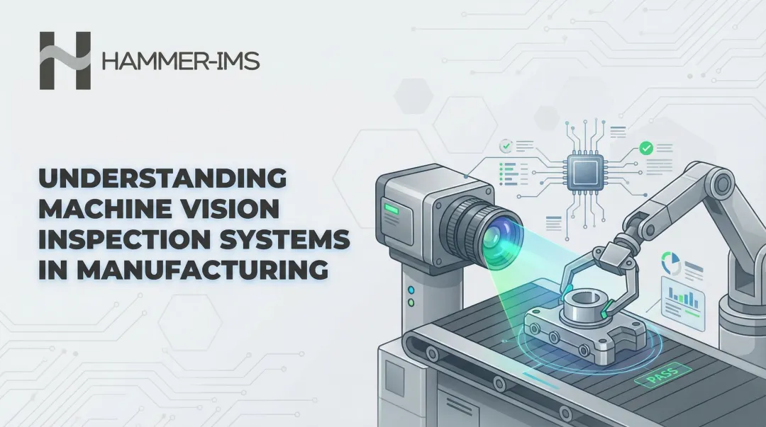
What Is Automatic Inspection with Machine Vision Technology?
Automatic inspection with machine vision combines industrial cameras, structured lighting, and computer vision software to evaluate products or materials on production lines without human intervention. These systems capture images, detect defects or deviations, and trigger real-time decisions—rejecting faulty parts, marking defective zones on continuous webs, or feeding data back to upstream process controls.
The term "machine vision" refers to the broader technology platform integrating hardware and software, while "automated visual inspection" (AVI) describes its application to quality control. The scope spans several distinct inspection tasks:
- Surface inspection: Pass/fail checks detecting scratches, contamination, and visible defects
- Dimensional measurement: Validating micron-level tolerances in geometry and positioning
- Material property analysis: Measuring thickness or density across continuous webs
The global machine vision market is projected to grow from USD 15.83 billion in 2025 to USD 23.63 billion by 2030, representing an 8.3% compound annual growth rate. Three forces are driving this growth: labor shortages, tighter regulatory requirements for traceability, and the push toward lights-out manufacturing where 100% inline inspection is mandatory.
Camera-based inspection, however, only captures what light can reveal. For industries producing continuous sheet materials—plastics, textiles, nonwovens, foam—quality is often defined by internal properties like thickness or basis weight, not surface appearance. Camera systems cannot measure these characteristics. That gap has driven adoption of beyond-visual sensing technologies, such as millimeter-wave (M-Ray) systems, which use electromagnetic signals to measure material properties contactlessly across the full width of moving webs.
Core Components of a Machine Vision Inspection System
Imaging and Illumination Hardware
Industrial cameras form the foundation of machine vision inspection. Two primary architectures dominate:
- Area-scan cameras capture 2D snapshots of discrete parts in a single frame, ideal for stationary or indexed production
- Line-scan cameras capture image data one line of pixels at a time, building complete images as material moves—critical for continuous web applications (paper, textiles, metal strip) and high-speed conveyors where motion blur would compromise area-scan images
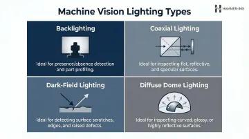
Structured lighting systems are equally critical. Poor illumination is universally cited as the primary cause of machine vision failure—even advanced cameras and algorithms cannot compensate for inadequate lighting. Lighting geometry fundamentally determines which defects are detectable:
- Backlighting creates silhouettes for presence/absence checks and hole detection but eliminates all surface detail
- Coaxial (on-axis) lighting transmits light perpendicular to the target via a beamsplitter, ideal for detecting flaws on highly reflective surfaces
- Dark-field lighting hits objects at low angles from the side, highlighting scratches and edges but providing poor overall dimensional contrast
- Diffuse dome lighting provides even illumination from multiple directions, minimizing glare on curved or shiny surfaces
Sensors and triggers detect when a product enters the inspection zone and fire cameras at precisely the right moment. On high-speed continuous lines, rotary encoders measure material speed and trigger image acquisition proportionally, ensuring images build correctly regardless of line speed fluctuations.
Processing and Software
The industrial computer processes each captured image through three sequential stages:
- Pre-processing — filtering, noise reduction, and normalization to prepare raw image data
- Feature extraction — algorithm-based identification of edges, dimensions, and anomalies
- Threshold comparison — measuring extracted features against predefined tolerance limits to flag or pass each part
Modern systems increasingly integrate AI and deep learning models alongside classical algorithms. Unlike rule-based approaches, deep learning software trains on annotated images and learns what a conforming part looks like. This lets the system tolerate unpredictable deviations and complex cosmetic defects that rigid algorithms would miss or misclassify.
How Automatic Machine Vision Inspection Works Step by Step
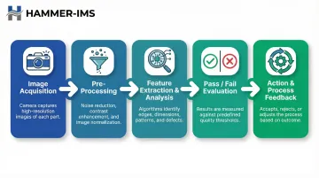
Step 1 — Image Acquisition
The system detects the incoming product via sensor trigger, fires lighting, and captures one or more images. Image quality at this stage is foundational. Blur, overexposure, or shadowing at acquisition cannot be corrected downstream—if the image is poor, the inspection fails regardless of software sophistication.
Step 2 — Pre-Processing
Raw images undergo filtering and normalization to isolate the region of interest, remove background noise, and standardize conditions. Flat-field correction compensates for non-uniform illumination across the sensor, while lowpass filtering smooths pixel data to reduce noise. These steps stabilize features and prepare images for analysis.
Step 3 — Feature Extraction and Analysis
Algorithms analyse processed images to extract measurable characteristics, including:
- Edge positions and dimensional coordinates
- Surface texture and colour values
- Signal data from non-visual sensors correlated to material thickness or density
The quality and design of these algorithms directly determine inspection speed and accuracy. Classical edge detection normalises peaks despite illumination changes, whilst deep learning models classify anomalies by comparing features to learned patterns.
Step 4 — Pass/Fail Evaluation
Extracted features are compared against pre-set tolerance windows defined by the manufacturer's quality standard. Objects or zones outside tolerance are classified as defective. The system generates a result—pass, fail, or flagged for review—for each inspected unit or segment.
Step 5 — Action and Process Feedback
The system translates results into actions:
- Rejecting a defective discrete part at the line
- Marking a defective zone on a continuous web for downstream removal
- Alerting an operator to a developing quality trend
- Feeding data back to upstream process controls to adjust parameters
Closed-loop feedback represents the most advanced application of machine vision. By automatically adjusting production settings in real time, it enables continuous process optimisation rather than simple defect detection.
Types of Automated Inspection: Surface, Dimensional, and Material Property Inspection
Surface and Visual Defect Inspection
Surface inspection detects scratches, cracks, stains, contamination, print errors, label placement issues, and other visible anomalies. This is the most common form of machine vision inspection, relying on camera-based imaging with appropriate lighting geometry.
The key challenge: surface inspection requires careful defect cataloguing upfront. The software must be trained to distinguish acceptable variation—natural material texture, expected colour shifts—from true defects. Without comprehensive training data, systems generate high false-reject rates or miss subtle defects entirely.
Dimensional and Geometric Inspection
Dimensional inspection measures the size, shape, position, or alignment of product features against specification. This is more deterministic than surface inspection because tolerances are mathematically defined: a hole diameter must be 5.00 mm ± 0.02 mm, with no subjective judgment required.
Common in precision component manufacturing—electronics, automotive parts, medical devices—dimensional inspection often employs telecentric lenses to eliminate parallax error, ensuring magnification remains constant regardless of object depth. 3D machine vision systems have expanded capability here, enabling volumetric measurement and height profiling that 2D imaging cannot provide.
Beyond-Visual Inspection: Measuring What Cameras Cannot See
Camera-based machine vision is strictly limited to surface properties. Yet for industries producing continuous sheet, film, nonwoven, or textile materials, quality is often defined by internal or cross-sectional properties—thickness, basis weight, density, or layer composition—rather than surface appearance alone. A surface image provides no information about whether the material is within thickness tolerance.
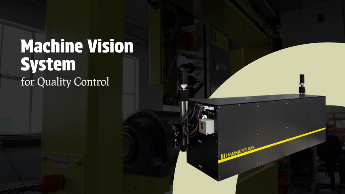
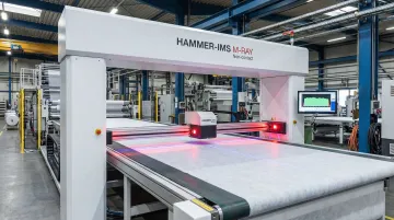
Non-visual sensing technologies extend machine vision beyond the camera. Millimeter-wave (M-Ray) technology uses electromagnetic signals at 60 GHz frequency to measure material thickness and density contactlessly across the full width of a moving web. The wave penetrates the material; the resulting time delay enables precise thickness calculation.
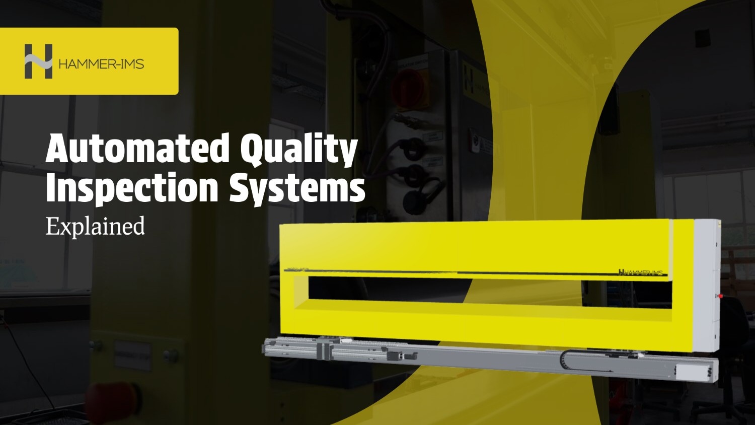
Hammer-IMS's M-Ray scanners are designed for this application, measuring thickness and basis weight across plastics, textiles, nonwovens, foam, and similar materials where camera-based systems fall short. Compared to nuclear gauges, M-Ray systems offer several practical advantages:
- No radiation safety protocols or special licensing required
- Non-contact measurement preserves material integrity on moving webs
- Full-width scanning delivers uniform coverage across the production line
- Reduced total cost of ownership without sacrificing measurement precision
Industries Using Machine Vision for Automated Inspection
Discrete Part Manufacturing
Discrete manufacturing spans several sectors, each with distinct inspection requirements:
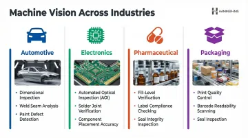
- Automotive: Dimensional inspection of precision components, weld seam quality verification, and paint defect detection
- Electronics: Specialised Automated Optical Inspection (AOI) systems for PCB defect detection, solder joint inspection, and component placement verification — 3D AOI systems now cover 50–55% of advanced PCB production lines
- Pharmaceutical/Medical: Fill-level verification, label compliance checking, seal integrity inspection, and component presence confirmation
- Packaging: Print quality, barcode readability, and seal inspection at line speeds exceeding 1,000 units per minute
Continuous Material Manufacturing
Continuous material production—textiles, nonwovens, plastic film, foam, steel strip—presents fundamentally different inspection challenges than discrete part manufacturing. Instead of inspecting individual units, these lines require full-width, continuous monitoring of material properties across kilometres of product.
Surface-based vision systems detect fabric or film surface defects—holes, stains, streaks, colour variation. Thickness and basis weight sensors monitor material consistency, enabling closed-loop feedback to production controls that adjust extrusion parameters, coating thickness, or fibre distribution as conditions change.
Hammer-IMS systems illustrate this directly: M-Ray sensors scan across web widths up to 5+ metres, measuring thickness and basis weight continuously whilst Edge-Vision camera systems detect surface defects. The combined data enables comprehensive quality control addressing both surface appearance and internal material properties.
Cross-Industry Adoption Drivers
Several factors accelerate adoption across all sectors:
- Increasing automation: Lights-out factories and dark manufacturing cells require 100% inspection without human oversight
- Labour shortages: With nearly half a million open manufacturing positions in the US alone, automated inspection addresses workforce gaps
- Stricter quality documentation: Regulatory standards like the FDA's Quality Management System Regulation mandate strict traceability, forcing adoption of automated data-logging inspection systems
- Material waste reduction: Real-time inspection data enables manufacturers to catch process drift earlier, reducing scrap generation
Benefits of Automating Quality Control with Machine Vision
Consistency and Speed
Machine vision systems operate at production line speeds without fatigue, bias, or shift-to-shift variability. Human visual inspection accuracy plateaus around 80% under ideal conditions and drops to 60-70% under real production conditions due to fatigue and monotony. AI-powered machine vision systems consistently achieve 99%+ detection accuracy.
100% inspection—checking every unit or every centimetre of material—is practically achievable with automation but physically impossible for human inspectors on high-speed lines. A single line-scan camera operating at 10,000 lines per second inspects material moving at 200 metres per minute with complete coverage. No human inspector can match this throughput.
Reduced Waste and Tighter Production Margins
Real-time inspection data, especially when fed back into production controls in a closed loop, allows manufacturers to detect and correct process drift before it generates significant scrap or off-spec material.
Systems capable of closed-loop adjustment—such as Hammer-IMS's Connectivity 3.0-enabled measurement solutions—allow continuous process optimisation, directly reducing material consumption and production thickness margins. By automatically adjusting extrusion die gaps, coating knife positions, or fibre distribution based on real-time measurement, manufacturers maintain tighter tolerances without manual intervention.
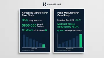
A documented aerospace manufacturer case study showed 35% scrap reduction and $805,000 annual savings after integrating AI vision with maintenance systems, achieving 12-month ROI. A panel manufacturer improved detection rates from 85% to 99.7% and reduced material waste by 75.3% through AI defect detection.
Data-Driven Quality Management
Tighter margins and reduced waste depend on one thing: knowing exactly what happened on the line and when. Automated inspection systems generate structured quality records for every unit produced, meeting traceability requirements increasingly mandated by customers and regulators across automotive, medical, and food supply chains.
Rather than sampling 1% of production and inferring overall quality, manufacturers capture complete data for 100% of output. That data enables:
- Traceability: Full quality records linked to individual production batches
- Statistical process control (SPC): Trend analysis that flags drift before it becomes scrap
- Shift performance comparison: Objective benchmarks across operators and time periods
- Root cause analysis: Correlating defect events with process parameters, maintenance logs, and material inputs
Frequently Asked Questions
What is a machine vision-based inspection system?
A machine vision-based inspection system combines industrial cameras, lighting, and computer vision software to automatically evaluate products or materials for defects, dimensional compliance, or material property deviations—replacing or augmenting human visual inspection on production lines.
How much does an AOI system cost?
AOI (Automated Optical Inspection) system costs vary from $3,200 for basic 2D hardware to $50,000–$200,000+ for advanced 3D systems, depending on inspection complexity, sensor type, line speed, and integration requirements (source). ROI is typically achieved within 1–3 years through reduced scrap, labour savings, and defect escape prevention.
What is the difference between machine vision inspection and manual inspection?
Machine vision delivers consistent, fatigue-free, high-speed inspection at 100% coverage. Manual inspection, by contrast, is subject to human error, fatigue, and sampling limitations, particularly on high-speed or continuous lines where complete coverage is physically impossible.
What industries benefit most from automated machine vision inspection?
Automotive, electronics, pharmaceuticals, packaging, food and beverage, and continuous material industries (textiles, nonwovens, plastics, steel) are primary adopters. The technology is applicable to any manufacturing process where consistent quality verification is required.
Can machine vision systems be integrated into existing production lines?
Yes. Most modern systems are designed for in-line integration and can be retrofitted to existing equipment, with complexity varying by line speed, mounting constraints, and whether closed-loop process feedback is required. Compact solutions like Hammer-IMS's Marveloc-CHARIOT need no additional lateral space, making them practical even on space-constrained lines.
What is the difference between 2D and 3D machine vision inspection?
2D systems capture flat images suitable for surface defect detection, colour verification, and basic dimensional checks. 3D systems generate depth or volumetric data enabling height measurement, warp detection, and complex geometric inspection. The right choice depends on which product characteristics define quality for your application.