Introduction
Battery cells powering EVs, smartphones, and grid-scale energy storage are hermetically sealed — once the casing closes and the electrolyte fill port is sealed, everything inside becomes invisible. That invisibility has a cost.
A misaligned electrode layer causes localized lithium plating that grows into dendrites, piercing the separator and triggering thermal runaway. A metal particle from electrode slitting shorts the anode to cathode. A microscopic weld crack allows moisture ingress, generating gas that swells the cell until it vents or bursts.
These are not rare edge cases. General Motors spent $1.9 billion to $2 billion recalling 2017–2022 Chevrolet Bolt EVs due to torn anode tabs and folded separators — defects invisible to conventional surface inspection. Hyundai faced a $900 million recall for similar fire risks in the Kona EV.
With global battery manufacturing capacity reaching over 3 TWh in 2024 and projected to hit 6.5 TWh by 2030, the industry needs scalable inspection methods that see inside sealed cells without destroying them.
X-ray Computed Tomography (CT) has become the gold-standard non-destructive technique for battery quality control and failure analysis. It removes the blind spot by rotating a cell 360° through an X-ray beam and reconstructing a full 3D volumetric map of electrodes, separators, particles, voids, and welds — all without opening or damaging the cell.
Key Takeaways
- X-ray CT maps sealed battery interiors in 3D, catching defects no external inspection can find
- Detects hidden defects including anode overhang deviations, electrode misalignment, metallic contamination, delamination, and weld flaws
- Three inspection modes cover different needs: 2D radiography for fast screening, laminography for pouch cells (~2 seconds), and full 3D CT for precise geometry (~20 seconds with AI)
- Used across the full battery lifecycle: R&D characterization, production quality gates, and post-failure root cause analysis
What Is X-ray CT Battery Inspection and Why It Matters
X-ray Computed Tomography (CT) is a 3D imaging technique in which a battery cell rotates 360° on a turntable between an X-ray source and detector. As it rotates, the system captures hundreds to thousands of 2D projection images from every angle.
A reconstruction algorithm combines these projections into a complete volumetric dataset: a cross-section map showing every internal layer, component, and void. Engineers can slice this 3D model in any plane, measure dimensions at the micron level, and identify defects that would otherwise stay invisible until the cell fails in service.
The core problem CT solves is fundamental to battery manufacturing: cells are hermetically sealed. Once the casing closes and electrolyte fills the cell, no surface inspection or contact measurement can reach inside.
Conventional electrical testing detects some defects — reduced capacity, higher internal resistance — but cannot pinpoint their physical cause or location. Defects like these can pass initial electrical screening and still cause failure months later:
- A bent electrode layer
- A copper fragment embedded in the separator
- A micro-crack in a tab weld
CT eliminates this blind spot, providing visual proof of each defect's size, position, and severity.
Where CT Fits in the Battery Lifecycle
- R&D and material development: High-resolution laboratory CT (voxel sizes down to 0.5 µm) lets engineers study electrode particle morphology, separator tortuosity, and active material distribution at the sub-micrometer level.
- Early production and process validation: First-article inspection uses CT to confirm that tooling, winding equipment, and welding parameters produce cells within dimensional tolerances.
- Volume manufacturing quality gates: Production-line CT systems built for 20-second scan times with AI reconstruction support at-line spot checks — screening finished cells for metal inclusions, welding voids, tab folding, and anode overhang before module assembly.
- Post-failure analysis: When cells fail in the field or during validation, CT delivers non-destructive root cause analysis, exposing internal shorts, delamination, and physical damage without disturbing the evidence.
Cell Formats and CT System Requirements
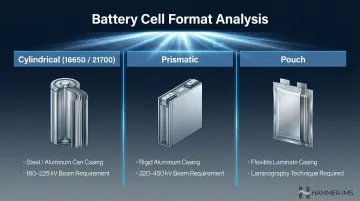
Different battery formats demand different X-ray energies and inspection setups:
| Cell Format | CT System Requirements |
|---|---|
| Cylindrical (18650, 21700) | High mechanical stability. Standard systems use 180 kV to 225 kV microfocus sources to penetrate the steel or aluminum can and dense jelly-roll structure. |
| Prismatic | Stacked or wound cells in rigid rectangular cases. Requires higher penetration power — 320 kV to 450 kV sources handle the thick, dense cross-sections. |
| Pouch | Flexible aluminum-laminated packaging. High aspect ratio causes photon starvation during 360° rotation; computed laminography (tilted-axis scanning) is recommended for fast, high-quality imaging. |
Key Defects X-ray CT Detects in Battery Cells
Battery cells contain layered, wound, or stacked structures assembled to tight dimensional tolerances — typically fractions of a millimeter. Even small manufacturing deviations create safety hazards or accelerate performance degradation. CT identifies five major defect classes that conventional inspection cannot reliably detect.
Anode Overhang Defects
The anode electrode must extend slightly beyond the cathode on all sides to prevent lithium plating at the edges during charging. Industry specifications typically target approximately 0.500 mm overhang.
Insufficient overhang causes lithium metal to plate directly onto the separator at the cell edges, where current density is highest. This plating grows into dendrites that pierce the separator and create internal short circuits. Excessive overhang, on the other hand, wastes active material, adds unnecessary weight, and can cause mechanical stress during winding or stacking.
CT precisely measures overhang geometry and bend radius in 3D across the full depth of the cell. A 2025 CT analysis of 1,054 cylindrical cells found 0% overhang failure in legitimate OEM cells, but 8% to 15% of low-cost and counterfeit brands exhibited dangerous negative overhang — where the cathode extends beyond the anode.
Electrode Misalignment
In both wound (jelly-roll) and stacked formats, anode and cathode sheets must align precisely. Misalignment — even by 0.2 to 0.3 mm — can compromise the separator, creating risk of direct electrode contact (internal short) or uneven current distribution that accelerates degradation and local hotspots.
CT detects misalignment across the full depth of the cell, revealing layer-by-layer deviations that 2D X-ray imaging cannot quantify due to projection overlap.
Foreign Particle Inclusions
Metallic fragments (commonly copper or aluminium from electrode cutting and slitting operations) become embedded inside cells during assembly. These particles can pierce the separator immediately or migrate during cycling, causing delayed internal shorts.
Detection sensitivity varies with particle density. High-density copper (8.92 g/cm³) and iron (7.87 g/cm³) particles appear clearly in CT scans, while low-density aluminium (2.70 g/cm³) is harder to distinguish against internal battery structure. Particles larger than 60 µm pose critical risk of bridging the cathode collector to anode active material. CT locates, measures, and classifies particles — enabling engineers to assess criticality and trace contamination back to specific production steps.
Delamination
Delamination is the separation of electrode coating from the current collector foil, or the separation of cell layers from one another. It occurs during manufacturing due to poor binder adhesion or calendering issues, or develops over the battery's service life as electrodes expand and contract during cycling.
CT reveals delamination as dark voids or gaps within the electrode stack. Measuring their extent helps engineers predict remaining service life and trace the root cause — often a binder formulation issue or excessive mechanical stress during assembly.
Weld and Seal Integrity
Battery assembly involves multiple critical welding and sealing steps: tab welding (connecting foil layers to current collectors), casing seam welds, and electrolyte fill port seals. Defective welds — containing pores, cracks, or incomplete fusion — allow moisture and air ingress that reacts with the electrolyte to produce gas, leading to cell swelling, venting, or fire.
CT identifies these failure points non-destructively, detecting:
- Post-weld dimensional distortion in casing seams
- Internal voids in ultrasonic welds as thin as 8 µm
- Seal integrity failures that surface inspection cannot detect
How Battery X-ray CT Inspection Works – Step by Step
CT inspection follows a logical workflow. Engineers go wrong by skipping setup validation (Step 2) or failing to connect inspection results to corrective action (Step 5). Here's the complete process.
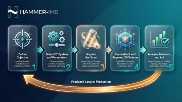
Step 1 – Define the Inspection Objective
Identify what the inspection must answer:
- Dimensional check for anode overhang?
- Contamination screen for foreign particles?
- Post-failure root cause analysis?
The answer drives every subsequent decision. Detecting a 10 µm metallic particle demands much higher resolution than measuring 0.5 mm electrode layer spacing — affecting CT system selection, scan time, and cost.
Step 2 – Select the Right CT System and Parameters
X-ray energy (kV), focal spot size, and detector type must match the cell's format and material composition.
System selection guidelines:
- Small cylindrical or pouch cells (R&D): 130-180 kV microfocus systems
- Standard cylindrical cells (18650, 21700): 180-225 kV systems
- Large prismatic cells or modules: 320-450 kV high-energy systems
Under-powered systems produce noisy images that miss defects. Over-powered systems reduce contrast between similar materials, making it harder to distinguish electrodes from separators.
Step 3 – Acquire the Scan
The battery cell mounts on a rotating stage between the X-ray source and detector. As it rotates through 360°, the system captures hundreds to thousands of 2D projection images from every angle.
Practical considerations:
- Scan time: Ranges from seconds (for 2D line-scan modes) to tens of minutes (for high-resolution 3D CT)
- Trade-offs: Speed vs. resolution vs. radiation dose to the sample
- Advanced techniques: AI reconstruction and Half.Turn CT (180-degree rotation) reduce cylindrical cell scan times to approximately 20 seconds without sacrificing image quality
Step 4 – Reconstruct and Segment the 3D Volume
A reconstruction algorithm combines all 2D projections into a 3D voxel volume. Two main approaches exist:
- Filtered Back-Projection (FBP): Fast but sensitive to noise and incomplete data — the standard choice for production environments where throughput matters.
- Iterative Reconstruction (such as SIRT): Slower, but delivers superior noise handling and artifact reduction, making it ideal for high-quality offline analysis.
Beam hardening correction is also critical. As polychromatic X-rays pass through dense battery materials, lower-energy photons are absorbed preferentially, causing the beam to "harden" (shift to higher average energy). This produces the "cupping" artifact: images appear artificially dark in the center and bright at the edges.
Two correction approaches address this. Hardware correction uses copper filters to strip low-energy X-rays before they reach the sample. Software correction applies polynomial or deep learning algorithms to suppress residual artifacts in the reconstructed volume.
After reconstruction, segmentation assigns different materials or phases to different voxel values, enabling quantitative measurement of individual layers, particles, or voids.
Step 5 – Analyze, Measure, and Act
Modern CT analysis software enables:
- Dimensional measurement: Layer thickness, overhang dimensions, particle size
- Defect detection: Automated flagging of anomalies against reference thresholds
- CAD comparison: Nominal-to-actual deviation mapping
The output must connect to action:
- Pass/fail decision for production
- Process parameter adjustment upstream (for example, replacing a worn slitting blade)
- Design change in R&D (for example, increasing overhang tolerance)
Without that feedback loop, CT inspection produces reports. With it, the process produces better batteries.
Putting It into Practice: A Battery CT Inspection Walkthrough
A manufacturer of prismatic lithium-ion cells for EV battery packs sees higher-than-expected capacity fade in cells that pass initial electrical testing. The QC team launches a CT inspection program to identify whether a structural cause is present.
What CT Revealed
3D reconstruction of sampled cells shows two recurring anomalies:
- Minor anode overhang variation at cell corners — within tolerance but near the lower limit
- Metallic particle contamination — small copper fragments concentrated near one edge of the electrode stack
Neither defect was detectable through standard electrical tests or 2D X-ray alone. 2D radiography showed faint shadows but could not resolve depth or confirm particle composition.
How Findings Drove Action
The copper fragments traced back to a worn slitting blade on one production line. After blade replacement, subsequent CT scans confirmed particle counts dropped back to normal levels.
The near-limit overhang, meanwhile, triggered a tooling adjustment in the winding equipment — tightening dimensional control and eliminating the edge-case lithium plating risk it had introduced.
Scaling the Solution
With root causes identified and corrected, the team turned to operationalizing those findings at volume. The CT analysis validated a faster inline 2D laminography inspection recipe tuned to the specific defect signatures CT had uncovered. Key outcomes of this approach:
- Screens for confirmed defect types at full line speed
- Extends inspection coverage across 100% of production cells
- Preserves full 3D CT capacity for periodic audits and post-failure analysis
How Hammer-IMS Can Help
X-ray CT addresses the challenge of inspecting finished, sealed battery cells. But quality control in battery manufacturing starts much earlier — at the electrode coating and separator film production stages. Consistent electrode coating thickness and uniformity directly determine cell energy density, cycle life, and safety margins.
Hammer-IMS provides non-nuclear, contactless measurement solutions that deliver real-time, inline thickness and uniformity data for battery electrode films and separator layers — helping manufacturers catch process deviations before they become defects in finished cells.
Key Differentiators for Battery Film Production Monitoring
- M-Ray technology measures thickness and basis weight contactlessly, with no radioactive sources — safe, clean, and suited to sensitive battery material environments. European regulators are increasingly restricting nuclear measurement licenses, making this a practical long-term advantage.
- Connectivity 3.0 software provides real-time closed-loop feedback to coating lines, correcting weight variation dynamically before out-of-tolerance material accumulates and reaches assembly.
- Integrated data logging and analytics give quality engineers the traceability and trend data needed for continuous improvement — complementing the structural detail that CT inspection provides at the finished-cell level.
Monitoring electrode coating thickness, separator film uniformity, and basis weight inline — throughout production — reduces the frequency and severity of defects that CT inspection would otherwise catch only after assembly is complete. That's the difference between a process correction and a scrapped cell.
Frequently Asked Questions
Can you X-ray a battery?
Yes, batteries can be X-rayed using 2D radiography or 3D Computed Tomography (CT), both of which are non-destructive and do not damage the cell. CT provides the most complete internal view, reconstructing a 3D map of electrode layers, separators, and any defects, and is routinely used in manufacturing quality control and R&D.
What is battery film?
Battery film refers to thin coated layers inside a cell: electrode films (anode and cathode coatings on metal foil current collectors) and separator film (a microporous membrane that isolates the anode from cathode while allowing ion transport). Controlling thickness and uniformity during production is critical to performance and safety.
What defects can X-ray CT detect in a battery cell?
CT detects five main defect types: anode overhang deviations, electrode misalignment, foreign particle inclusions, electrode delamination, and weld or seal integrity issues. It is the only non-destructive method capable of identifying all of these in a sealed cell, at sub-millimeter or micron-level precision depending on the system.
What is the difference between 2D X-ray and full 3D CT for battery inspection?
2D X-ray produces a single flat projection image, useful for fast screening of anode overhang and alignment issues, but cannot resolve depth or distinguish overlapping structures. Full 3D CT rotates the cell 360° and reconstructs a complete volumetric model, enabling detection of internal voids, particle locations, and layer-by-layer measurement, at the cost of longer scan time and higher system complexity.
What is the 80/20 rule for lithium batteries?
The 80/20 rule recommends charging to no more than 80% and discharging no lower than 20% of battery capacity during regular use. This reduces mechanical stress on electrodes from full expansion and contraction cycles, slowing electrode microstructure degradation and extending cycle life.
What does C mean on a battery?
"C" is the C-rate, a standard measure of charging or discharging current relative to battery capacity. A 1C rate means the battery fully charges or discharges in one hour; 2C in 30 minutes; 0.5C in two hours. Higher C-rates generate more heat and mechanical stress on electrode particles, which is why CT is used in R&D to study electrode degradation at different C-rates.