In modern manufacturing, whether in aerospace, automotive, electronics, medical devices, or precision engineering, surface cleanliness is not just a matter of aesthetics. Even microscopic contamination (particles, oils, residues, oxidation) on optical surfaces can compromise product integrity or lead to failures in critical applications.
As manufacturing tolerances tighten and regulatory and quality standards rise, detecting and eliminating surface contamination early becomes a strategic imperative rather than an afterthought.
The concept of “Cost of Poor Quality” (COPQ) shows that quality-related failures (including defects, rework, scrap, recalls, returns) can consume between 15% to 20% of sales revenue for many companies. In some cases, quality-related costs can escalate to as much as 40% of total operations costs.
These figures make clear that contamination, a subset of quality issues, is not a trivial detail but a potential cost driver that can deeply affect profitability, brand reliability, safety, and compliance.
In this guide, we will define what constitutes “optical surface contamination,” examine why it matters, explore the optical technologies and inspection workflows used to catch contamination early, and present best practices for integrating contamination inspection into manufacturing quality systems.
Key Takeaways
Microscopic particles, oils, residues, and oxidation can cause product failures, compliance risks, and operational losses of up to 40% COPQ.
Modern optical inspection combines 2D/3D imaging, hyperspectral/UV/IR techniques, and AI algorithms to detect contaminants invisible to the naked eye.
High-performance setups optimize lighting, optics, sensors, and environmental control, with inline systems enabling real-time defect prevention and offline systems supporting deep diagnostics and root-cause analysis.
KPIs like detection accuracy, false-positive rate, R&R, defect escape rate, and Cp/Cpk help manufacturers track performance, improve processes, and ensure regulatory compliance.
What Qualifies as Surface Contamination?
Surface contamination refers to any unwanted substance, particle, film, or residue present on a component’s surface that can interfere with performance, reliability, assembly, coating, bonding, or regulatory acceptance.
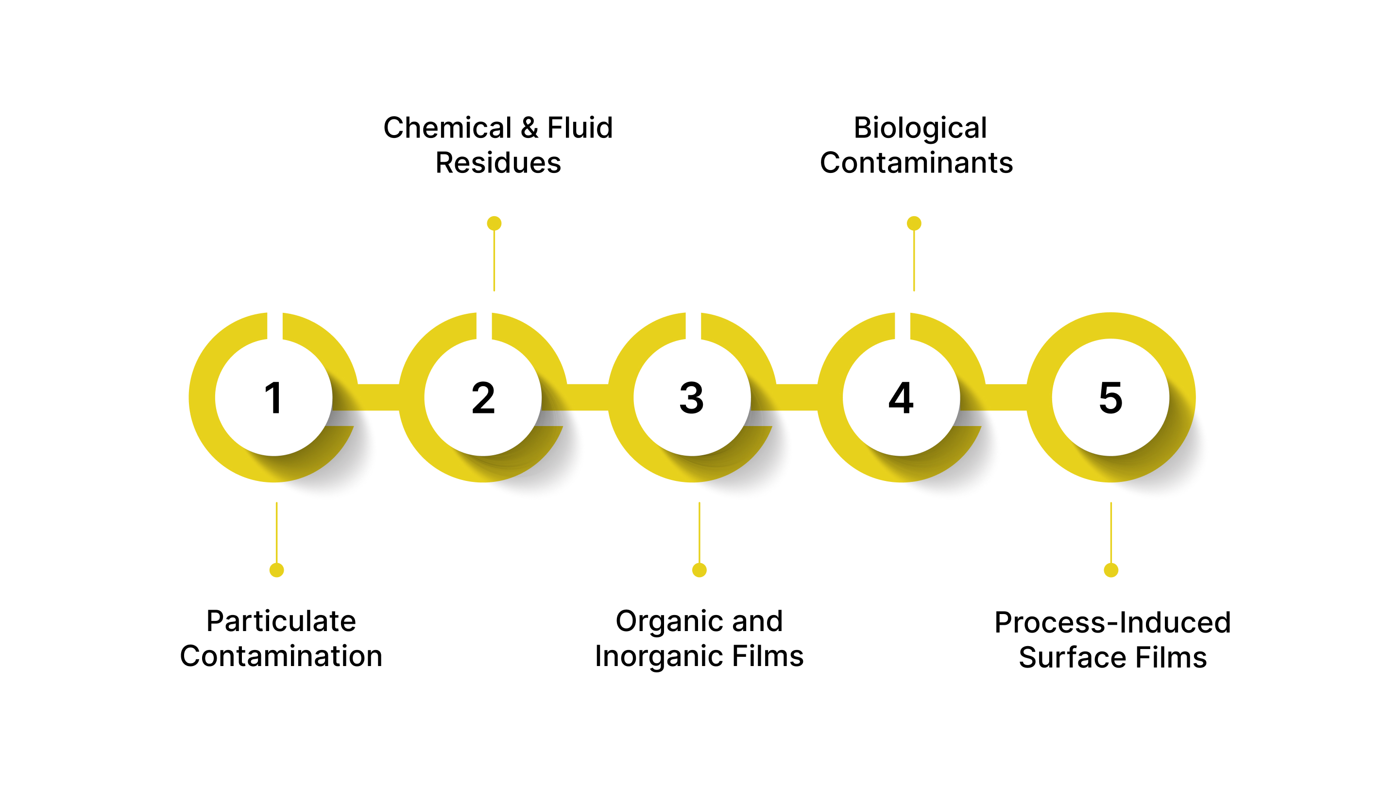
Below are the major categories:
1. Particulate Contamination
Unwanted solid particles get loosely or firmly attached to a surface. Common examples include:
Dust, lint, cotton fibers
Machining debris, burrs, metal shavings
Environmental particulates from HVAC or human handling
Submicron particles in semiconductor and optical component manufacturing
These typically show up as high-contrast spots or shapes in optical inspection systems.
2. Chemical and Fluid Residues
Leftover liquids or films from processes like machining, assembly, cleaning, or human contact. Includes:
Fingerprints (oils, salts)
Coolants and cutting fluids
Lubricants and greases
Solvents and cleaning agent residues
These contaminants often require UV/fluorescence or spectral imaging to detect, especially on reflective or textured surfaces.
3. Organic and Inorganic Films
Thin, often invisible layers that alter the surface’s optical or functional properties. Examples:
Oxidation layers or corrosion products
Coating overspray or mist
Silicone films from release agents
Adhesive smears or polymer residues
Such films can disrupt bonding, welding, painting, or sealing, making them critical to identify early.
4. Biological Contaminants (Selective Industries)
Relevant in medical devices, biotech, optics, and cleanroom manufacturing. These may include:
Skin cells
Microbial residues
Biofilms or organic debris
Although less common in general manufacturing, they pose a high regulatory risk in FDA-regulated environments.
5. Process-Induced Surface Films
Unintentional byproducts created during fabrication. Includes:
Burn marks or carbon deposits
Weld spatter
Laser cutting residue
Powder overspray (additive manufacturing)
These defects blur the line between “contamination” and “surface damage,” but functionally, they still compromise quality and thus require detection.
Why Optical Contamination Inspection Matters?
Surface contamination may seem small, but its consequences can be severe, impacting product performance, regulatory approval, safety, and long-term reliability. For U.S. manufacturers operating in highly regulated sectors, optical contamination inspection isn’t just a quality step; it's a strategic requirement.
1. Prevents Product Failures and Performance Issues
Contamination can disrupt coating adhesion, interfere with bonding or welding, weaken protective layers, or create optical distortions. In industries like aerospace or medical devices, even microscopic residues can compromise mission-critical performance.
2. Ensures Compliance With U.S. Standards
Many industries mandate strict surface cleanliness benchmarks:
AS9100 for aerospace
IATF 16949 for automotive
FDA 21 CFR Part 820 for medical devices
ISO 14644 for cleanroom manufacturing
Optical inspection ensures contaminants are detected early enough to meet these regulatory thresholds.
3. Supports Traceability, SPC, and Digital Quality Systems
Optical inspection systems integrate easily with PLCs, MES, and SPC dashboards. This allows manufacturers to:
Track defect trends
Correlate contamination with upstream processes
Maintain digital audit trails for FDA or DoD compliance
Strengthen continuous improvement programs
4. Improves Throughput Without Sacrificing Accuracy
Modern optical systems detect microscopic contaminants at high speeds, allowing continuous inspection without slowing production. This supports U.S. manufacturers’ push toward automation, lights-out manufacturing, and real-time quality assurance.
5. Reduces Risk of Recalls and Field Failures
Surface contamination is a hidden, but common, cause of field failures in coatings, electronics, and sealing applications. By catching defects earlier, manufacturers reduce the risk of:
Component failures in the field
Customer returns
Warranty repairs
Reputation damage
Core Optical Inspection Technologies
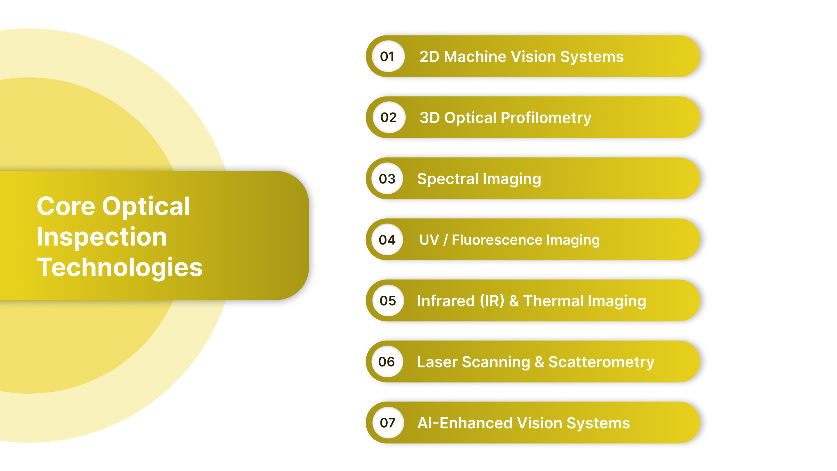
Optical contamination detection relies on a range of imaging technologies, each suited for specific surface conditions, materials, and defect types. Below are the core systems widely used across U.S. aerospace, medical device, automotive, electronics, and semiconductor manufacturing.
1. 2D Machine Vision Systems
Traditional 2D imaging is the backbone of most contamination inspection setups.
How it works: High-resolution cameras capture surface images under controlled lighting, allowing software to detect contrast differences caused by particles, smudges, stains, or scratches.
Best for:
Dust, fibers, machining debris
Stains, smudges, fingerprints
Painted, coated, or reflective surfaces with stable lighting
2. 3D Optical Profilometry
3D systems measure height variations, making them ideal for contaminants that sit above or below the surface.
How it works: Structured light, laser triangulation, or confocal scanning captures depth maps with micron-level accuracy.
Best for:
Burrs, metal shavings, chips
Dried residues creating height irregularities
Additive manufacturing powder contamination
3. Hyperspectral & Multispectral Imaging
Advanced spectral imaging distinguishes contamination types based on their chemical signatures.
How it works: The camera captures dozens to hundreds of wavelengths, detecting differences invisible to standard vision systems.
Best for:
Oil residues, cleaning agent films
Organic/inorganic surface films
Coating overspray, release-agent smears
4. UV / Fluorescence Imaging
Fluorescence enhances the visibility of contaminants that normally blend into the surface.
How it works: UV light excites certain residues, causing them to emit visible light that cameras can detect.
Best for:
Oils, greases, lubricants
Fingerprints and skin oils
Certain adhesives and sealants
5. Infrared (IR) and Thermal Imaging
Infrared reveals temperature or absorption differences associated with moisture or certain chemical residues.
How it works: IR sensors detect thermal or spectral absorption patterns indicative of contamination.
Best for:
Moisture, water spots, condensation
Residues that absorb/reflect IR differently
Thermal defects caused by process contamination
6. Laser Scanning & Scatterometry
Laser-based systems detect minute contamination and surface irregularities through how light scatters.
How it works: A laser beam is projected at the surface, and the scattering pattern is analyzed.
Best for:
Submicron particles
Optical components, lenses, wafers
High-gloss or precision-polished surfaces
7. AI-Enhanced Vision Systems
Modern optical inspection increasingly uses AI to improve detection accuracy.
How it works: Deep learning models analyze camera data to identify subtle contamination patterns that rule-based systems may miss.
Best for:
Complex surfaces with variable textures
Mixed-material assemblies
High-speed lines where false positives must be minimized
Key Elements of a High-Performance Inspection Setup
Building a reliable contamination inspection system requires more than choosing the right camera. Real performance comes from optimizing lighting, optics, sensor selection, and environmental control so contaminants become unmistakably visible.
Below are the foundational elements every manufacturer should consider.
1. Lighting: The Most Critical Variable
Lighting defines how contaminants appear, or disappear, in captured images.
Key lighting strategies include:
Bright-field illumination: Best for general surface inspection; highlights contrast.
Dark-field / low-angle lighting: Excellent for particles, scratches, and raised contaminants.
Coaxial or on-axis lighting: Ideal for reflective surfaces such as metals, glass, and coated parts.
Raking light (angled): Reveals texture changes, smears, and thin films.
2. Optics: Field of View vs. Resolution
The lens determines how clearly contaminants appear in the image.
Key considerations:
Field of View (FOV): Larger FOV means faster coverage but lower resolution.
Working Distance (WD): Crucial for tight spaces or robotic integration.
Magnification: Required when detecting micron-level contamination or thin films.
Lens coatings: Anti-reflection coatings help stabilize imaging for reflective U.S. manufacturing surfaces (machined metals, glass, medical plastics).
3. Camera & Sensor Selection
Cameras must capture clear, distortion-free data at production speeds.
Key choices:
Sensor type: Industrial CMOS dominates modern systems due to high speed and low noise.
Resolution: Higher resolution improves the detection of small contaminants but increases the processing load.
Frame rate: Essential for inline, high-speed manufacturing lines.
Global vs. rolling shutter: Global shutter is preferred for moving parts, avoiding distortion.
4. Image Processing Hardware
The backend determines how quickly and accurately contamination is identified.
Options include:
Edge processors / embedded systems: Low latency, ideal for real-time decision-making.
GPU-accelerated hardware: Required for deep learning/AI contamination detection.
Industrial PCs: Common in legacy systems needing flexibility and expandability.
5. Environmental Controls
Variability in the environment can drastically affect inspection accuracy.
Key factors:
Temperature & humidity: Impact optical performance and can introduce condensation or fogging.
Vibration isolation: Crucial for microscopes, profilometers, and systems using structured light.
Cleanliness level: Semiconductor, optics, and medical device plants may require ISO Class 5–8 cleanrooms.
Airflow direction: Prevents particles from accumulating on parts during inspection.
6. Part Handling & Positioning
How the part is presented to the camera determines repeatability.
Essential elements:
Fixtures and nests to ensure consistent orientation.
Controlled conveyor speed to prevent motion blur.
Precision robotics for multi-angle inspection (common in aerospace and EV battery manufacturing).
Anti-static mechanisms to prevent dust from attracting to charged surfaces.
7. Software & Algorithm Calibration
A high-performance setup is only as strong as its detection logic.
Requirements:
Repeatable thresholds for particle size, contrast, and defect boundaries.
AI/ML models trained on real contamination samples from U.S. production lines.
Adaptive lighting controls to compensate for material differences.
Real-time SPC integration for trend analysis, Cp/Cpk, and automated alerts.
8. Integration With U.S. Manufacturing Systems
Inspection systems must fit seamlessly into existing automation infrastructure.
Typical integrations:
PLC systems: Rockwell, Siemens, Beckhoff
MES/ERP platforms: Ignition, SAP, Plex
Barcode/UID tracking: Required for aerospace & defense traceability
Quality records: FDA-compliant audit trails for medical devices
Inline vs Offline Contamination Inspection
Choosing between inline and offline inspection depends on production speed, tolerance requirements, regulatory demands, and the criticality of the part. Both approaches play distinct roles in ensuring surface cleanliness.
Factor | Inline Inspection | Offline Inspection |
|---|---|---|
Location | On the production line (continuous flow) | Lab, metrology room, or standalone cell |
Speed | Very fast; real-time at line speed | Slower; manual or semi-automated |
Resolution / Detail | Moderate; optimized for speed | Very high; optimized for accuracy |
Typical Tools | 2D/3D vision, AI vision, laser sensors, high-speed cameras | Microscopes, profilometers, hyperspectral/UV/IR systems |
Primary Purpose | Immediate detection before downstream operations | Deep analysis, validation, root-cause investigations |
Feedback Loop | Instant process feedback and alarms | Delayed; results used for periodic adjustments |
Labor Requirement | Low; mostly automated | Moderate to high; requires skilled technicians |
Best For | High-volume production (automotive, electronics, packaging) | High-precision parts (aerospace, semiconductors, medical devices) |
Advantages | Reduces scrap, improves throughput, enables SPC integration | Highest accuracy, flexible imaging, robust diagnostics |
Limitations | Limited depth/detail; sensitive to lighting and part presentation | Not real-time; sampling risk; slower cycle times |
Cost Consideration | Higher integration cost; lower long-term manual inspection cost | Lower integration cost; higher labor/equipment intensity |
Common Use Cases | Detecting debris, smudges, fingerprints, and residues on fast-moving parts | Investigating chemical films, submicron particles, oxidation, and coating issues |
Typical Contaminants & Detection Methods
Optical inspection systems rely on contrast, reflectivity, height differences, and spectral signatures to identify contamination. Different contaminants interact with light in distinct ways, making certain imaging methods more effective. Below is an engineering-focused breakdown of the most common contaminants and how modern optical systems detect them.
Contaminant Type | Description | Detection Techniques | Key Industries |
|---|---|---|---|
Dust, Fibers, Particulates | Loose or attached particles (dust, lint, machining debris, metal shavings) | 2D vision (contrast detection), Dark-field lighting, 3D profilometry | Electronics, Automotive, Aerospace, EV batteries |
Oils, Greases, Lubricant Residues | Films from machining, handling, assembly, or lubrication | UV/fluorescence imaging, Hyperspectral imaging, Polarized lighting | Automotive, Aerospace, Medical devices |
Fingerprints / Skin Oils | Human-origin residues containing oils, salts, and moisture | Oblique/raking light, UV illumination, AI-enhanced vision | Medical devices, Optics, Cleanrooms |
Chemical Cleaning Agent Residues | Solvent, detergent, or wash fluid remnants | Hyperspectral imaging, IR imaging, Gloss/reflectivity measurement | Medical devices, Aerospace, Precision machining |
Coating Overspray / Mist | Unintentional deposition of paints, primers, and adhesives | Color/contrast imaging, 3D profilometry, Laser scatterometry | Automotive, Aerospace, Industrial coatings |
Oxidation, Rust, Corrosion Films | Chemical surface degradation causes discoloration or roughness | Spectral imaging, 3D profilometry, AI models | Aerospace, Heavy machinery, Oil & Gas components |
Moisture / Condensation / Water Spots | Liquid droplets or drying marks affecting adhesion/coatings | IR imaging, Polarized lighting, Dark-field illumination | Electronics, Optics, Coating lines |
Additive Manufacturing Powder Residue | Loose or semi-fused powder left post-3D printing | 3D scanning, Laser scatterometry, AI vision | Aerospace, Medical implants, Tooling components |
Inspection Key Performing Indicators (KPIs) for Manufacturers
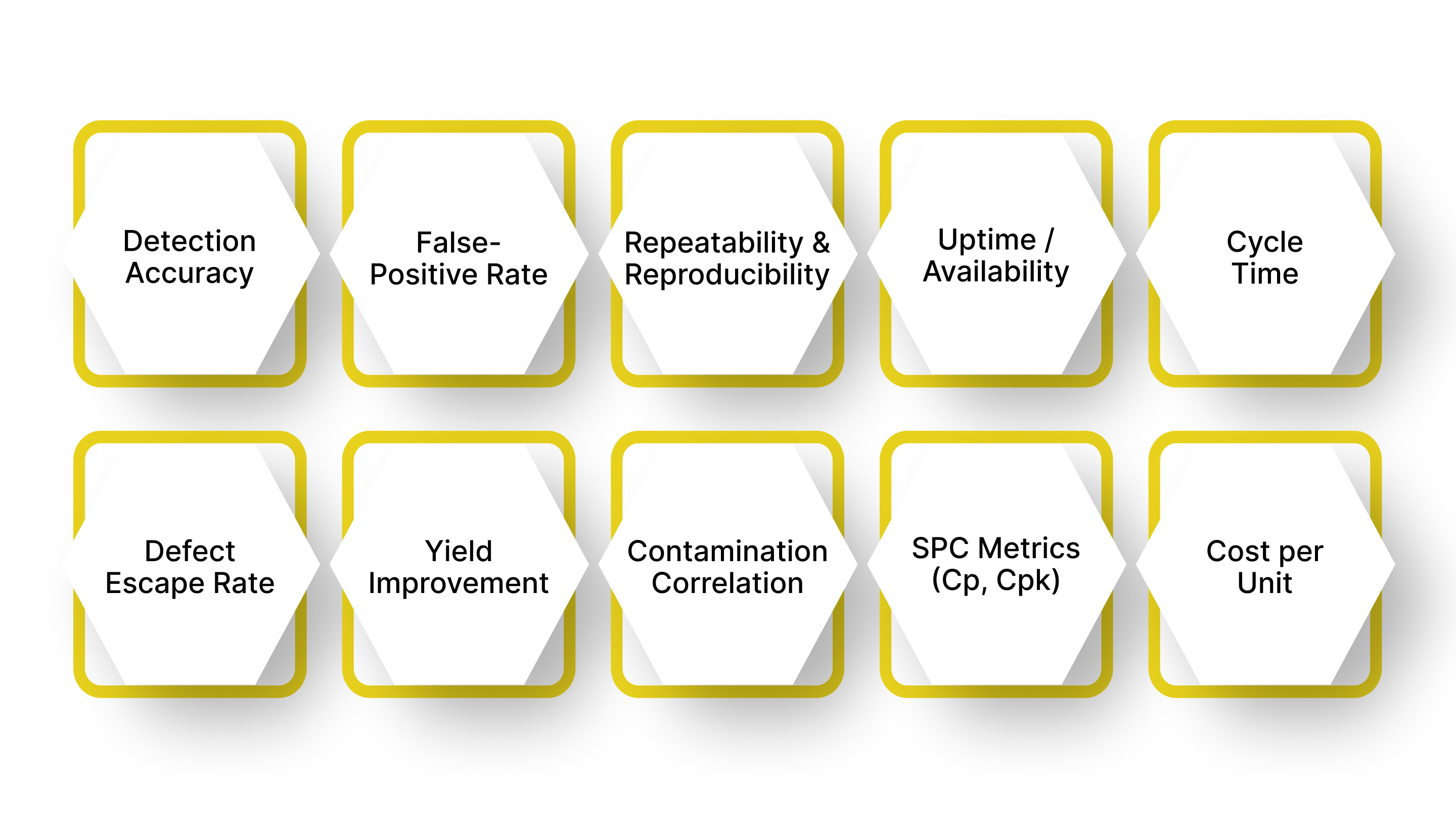
Effective surface-contamination control depends on continuous measurement, not assumptions. The KPIs below help manufacturers evaluate optical inspection performance, process stability, and quality consistency.
Detection Accuracy: Measures how reliably the system identifies true contamination events.
False-Positive Rate (FPR): Percentage of clean parts incorrectly flagged as contaminated.
Repeatability & Reproducibility (R&R): Evaluates consistency across operators, shifts, lighting conditions, and part variations.
Uptime / System Availability: Percentage of time the inspection system is operational and not under recalibration or maintenance.
Cycle Time / Inspection Speed: Time taken to inspect each part.
Defect Escape Rate: Rate at which contamination passes inspection and reaches downstream stations, or worse, customers.
Yield Improvement: Change in first-pass yield (FPY) after implementing optical inspection.
Contamination Source Correlation: Ability to link detected contaminants to upstream process steps (e.g., coating, machining, packaging).
SPC Metrics: Cp and Cpk: Inline inspection data feeds process capability metrics.
Cost per Inspected Unit: Total inspection cost divided by the number of units inspected.
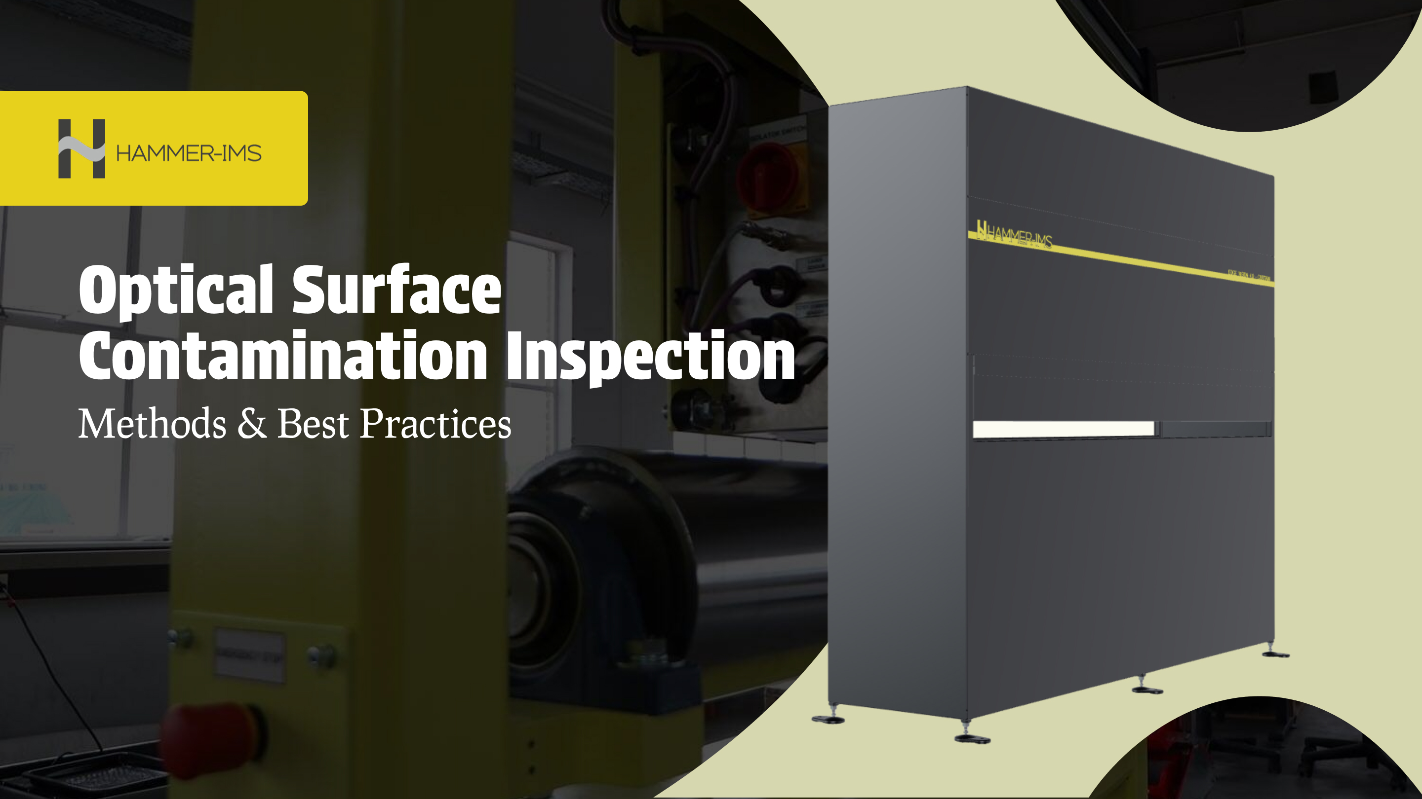
Why Hammer-IMS Matters for Optical & Surface-Contamination Inspection
When aiming for high-precision, reliable contamination detection or process control, Hammer-IMS stands out as a strong partner, especially for manufacturers in the U.S. or globally who care about safety, sustainability, and inline inspection robustness.
Radiation-free, non-contact measurement technology: Ueverages its proprietary electromagnetic “M-Ray” technology to measure thickness and basis-weight without relying on nuclear sources. This ensures a safer, environmentally friendly inspection solution.
High precision and real-time inline inspection: Systems are built for continuous production lines, ideal for industries handling textiles, nonwovens, plastics, battery films, coatings, composites, and more.
Surface inspection with modern vision systems: The “Edge-Vision-4.0” line combines machine-vision and optionally AI-based classification to spot surface defects, foreign objects, coating irregularities, or contamination even before downstream processes.
Customizable & integrable solutions: Supports multiple configurations (sensor type, mechanical platforms like CURTAIN/CHARIOT/CIRCLE, multi-sensor setups) and integrates with production systems, making it feasible for different manufacturing use-cases.
If you’re ready to explore a high-performance, non-destructive, and sustainable inspection solution tailored to modern manufacturing demands, book a demo today.
Conclusion
Today’s factories cannot rely on manual detection alone. High-precision optical systems deliver the consistency, speed, and traceability needed to keep operations competitive. Understanding contamination sources and selecting the right inspection technologies can help build inspection programs that find defects and prevent them at the process level.
Investing in optical contamination inspection is ultimately an investment in reliability, yield, and brand reputation. Plants that integrate these systems effectively will reduce scrap, strengthen compliance, accelerate throughput, and achieve a measurable competitive advantage.
Ready to enhance your contamination control and inline measurement capabilities? Explore how Hammer-IMS’s radiation-free, high-precision inspection systems can strengthen your production quality.
Request a demo or speak with a specialist about the best solution for your line.
FAQs
1. What industries face the highest risk from microscopic surface contamination?
Sectors like medical devices, aerospace, semiconductors, optics, and EV battery manufacturing face the greatest risk because even submicron particles can impact safety, performance, or regulatory compliance.
2. How often should manufacturers recalibrate optical inspection equipment?
Most systems require calibration every 6–12 months, depending on usage intensity, environmental conditions, and manufacturer recommendations. High-precision industries may calibrate more frequently.
3. Can optical inspection systems detect chemical contamination or only physical particles?
Advanced systems, especially hyperspectral, UV fluorescence, and infrared imaging, can detect chemical films, residues, and surface energy changes that are invisible to standard cameras.
4. How do environmental factors affect contamination detection accuracy?
Temperature shifts, vibration, ambient lighting, and airborne dust can influence readings. Many facilities use isolation mounts, enclosed lighting, and air filtration to stabilize inspection conditions.
5. Are optical contamination systems compatible with automation platforms like PLCs and MES?
Yes. Modern systems support integration with PLCs, MES, SCADA, and SPC software, enabling automated reject mechanisms and real-time quality dashboards.
6. What’s the biggest misconception about optical contamination inspection?
Many manufacturers assume high-resolution cameras alone are enough. In reality, lighting geometry, optical filters, and AI algorithms often make a greater contribution to defect detectability.
7. Do inspection systems require specialized operators?
Most inline platforms are fully automated after setup, but advanced offline systems, such as hyperspectral or confocal microscopy, benefit from trained technicians who understand imaging and materials.