Quality control has become one of the most pressing challenges for U.S. manufacturers. According to the 2025 ETQ “Pulse of Quality in Manufacturing” survey, 70% of manufacturers report that labor shortages directly impact inspection capacity, and 88% say these shortages hurt product quality.
At the same time, defect-related risks remain costly. 75% of manufacturers experienced at least one recall in the past five years, with nearly half reporting losses between $10 million and $50 million per incident.
As production volumes rise, tolerance tightens, and regulatory demands increase across sectors like aerospace, automotive, electronics, and pharmaceuticals, the limitations of manual visual inspection have become more apparent.
Human inspectors struggle with micro-defect visibility, consistency across shifts, and the speed required for modern high-throughput lines.
This is where optical defect inspection systems have become indispensable. These automated, camera-based technologies detect scratches, cracks, dimensional deviations, contamination, surface irregularities, and assembly errors at speeds human inspectors cannot match.
This guide provides a complete, technically grounded overview of optical defect inspection systems.
TL;DR
Optical defect inspection systems detect micro-defects far beyond human capability, ensuring consistent, high-accuracy quality control across fast, high-volume manufacturing lines.
Unlike manual inspection, optical systems maintain uniform performance across all shifts, providing millisecond-level inspection without operator fatigue or variability.
High-resolution cameras, engineered lighting, and AI models identify subtle, low-contrast, or complex defects that traditional rule-based or manual methods often miss.
Seamless connectivity with PLCs, MES, and automation enables instant corrections, defect rejection, and data-driven process optimization, minimizing scrap and costly product recalls.
Optical inspection systems scale easily with added cameras, sensors, or AI models, supporting production expansion and meeting strict regulatory and industry quality standards.
What Are Optical Defect Inspection Systems?
Optical defect inspection systems are automated vision-based technologies that use industrial cameras, precision lighting, sensors, and advanced image-processing algorithms to detect visual, structural, or dimensional defects in manufactured products.
Unlike manual inspection, these systems capture high-resolution images in milliseconds and analyze them using deterministic rules, Machine Learning (ML), or deep learning models to identify deviations from required specifications.
At their core, optical inspection systems perform three critical functions:
Capture visual or 3D surface data with consistent lighting and calibration.
Analyze that data to identify abnormalities, variations, or defects.
Classify and decide whether the part passes, fails, or requires re-inspection.
What Types of Defects Can They Detect?
Modern systems can identify a wide range of defects, including:
Scratches, pits, dents, and cracks
Surface contamination (oil, particles, foreign materials)
Dimensional deviations (gap/flush, height, warping, deformation)
Missing, rotated, or misaligned components
Weld defects, solder bridging, voids, and insufficient fill
Coating variation or discoloration
Seal integrity issues (in pharma/food packaging)
Texture inconsistencies (in film, paper, sheet metal, plastics)
Many high-end systems can detect defects below 20–50 microns, depending on sensor type and optical configuration.
Why Manufacturers Use Optical Inspection
Optical inspection plays a vital role in modern quality control because it offers:
High repeatability and accuracy, regardless of operator fatigue
Micron-level detection beyond the capability of the human eye
High throughput, matching production line speeds
Objective, traceable decisions instead of subjective human judgment
Real-time feedback to reduce scrap and improve upstream processes
Compliance support for industries governed by strict standards (IATF 16949, AS9100, FDA/GMP)
Where Optical Inspection Is Commonly Used
In the U.S., optical defect inspection systems are widely deployed in:
Automotive (surface finish, welds, EV battery cells, assemblies)
Electronics (SMT/AOI, semiconductor wafer inspection, PCB quality)
Aerospace (machined part tolerances, composite defects, turbine blades)
Packaging (labels, barcodes, seals, fill-level checks)
Pharmaceuticals (tablet inspection, blister pack integrity, contamination)
Food & Beverage (caps, seals, color consistency, foreign matter)
Metals & Materials (coil inspection, surface defects, sheet uniformity)
By providing consistent, fast, and measurable inspection, these systems help manufacturers reduce scrap, minimize recalls, improve customer satisfaction, and maintain production stability even with reduced labor availability.
How Optical Inspection Differs from Manual Inspection
Manual visual inspection has been a cornerstone of quality control for decades, but it has inherent limitations related to human perception, fatigue, and environmental variability. As product complexity increases and tolerances become tighter, relying on manual inspection alone can introduce inconsistency, missed defects, and higher operational costs.
Optical defect inspection systems overcome these limitations by combining high-resolution imaging, controlled lighting, and algorithmic decision-making to deliver repeatable, objective, and traceable quality results at production-line speeds.
Below is a refined, more detailed comparison that highlights key differences important to manufacturing operations.
Factor | Manual Inspection | Optical Inspection Systems |
|---|---|---|
Consistency | Varies by operator skill, fatigue, lighting, and shift changes. | Delivers uniform results with no fatigue; unaffected by environmental variability. |
Limited by human vision (typically ~50–100 microns). Struggles with subtle, low-contrast defects. | Detects micro-defects (<20 microns) with high-resolution cameras and advanced algorithms. | |
Speed | Slow and inconsistent; cannot keep up with high-speed automated lines. | Inspects parts in milliseconds; supports high-throughput and continuous motion lines. |
Error Rates | Higher probability of missed defects and false passes; subjective judgment. | Low error rates with objective, repeatable detection; AI models reduce false positives. |
Traceability | Limited documentation; often manual logs that are prone to error. | Generates digital images, defect maps, timestamps, and audit-ready reports. |
Cost Efficiency | Labor-intensive; higher long-term cost due to rework, scrap, and workforce scaling. | Reduces scrap, rework, and labor requirements; lower cost per part over time. |
Scalability | Difficult to scale without hiring, training, and retaining additional inspectors. | Easily scales with added cameras, sensors, computing power, or AI models. |
Inspection Complexity | Struggles with small, reflective, textured, or fast-moving parts. | Handles complex surfaces, low-contrast features, 3D shapes, and reflective materials with advanced optics. |
Data & Analytics | Minimal or no data captured; no automated trend visibility. | Provides real-time analytics for SPC, defect trends, root cause analysis, and predictive maintenance. |
Suitability | Best for low-volume, high-variation, or prototype inspections. | Ideal for high-volume, repetitive, high-precision manufacturing environments. |
How Optical Defect Inspection Systems Work
Optical defect inspection systems capture visual or 3D data of a product and use advanced algorithms to detect deviations from the expected standard. A complete inspection workflow integrates cameras, optics, lighting, sensors, processing hardware, AI software, and automation controls.
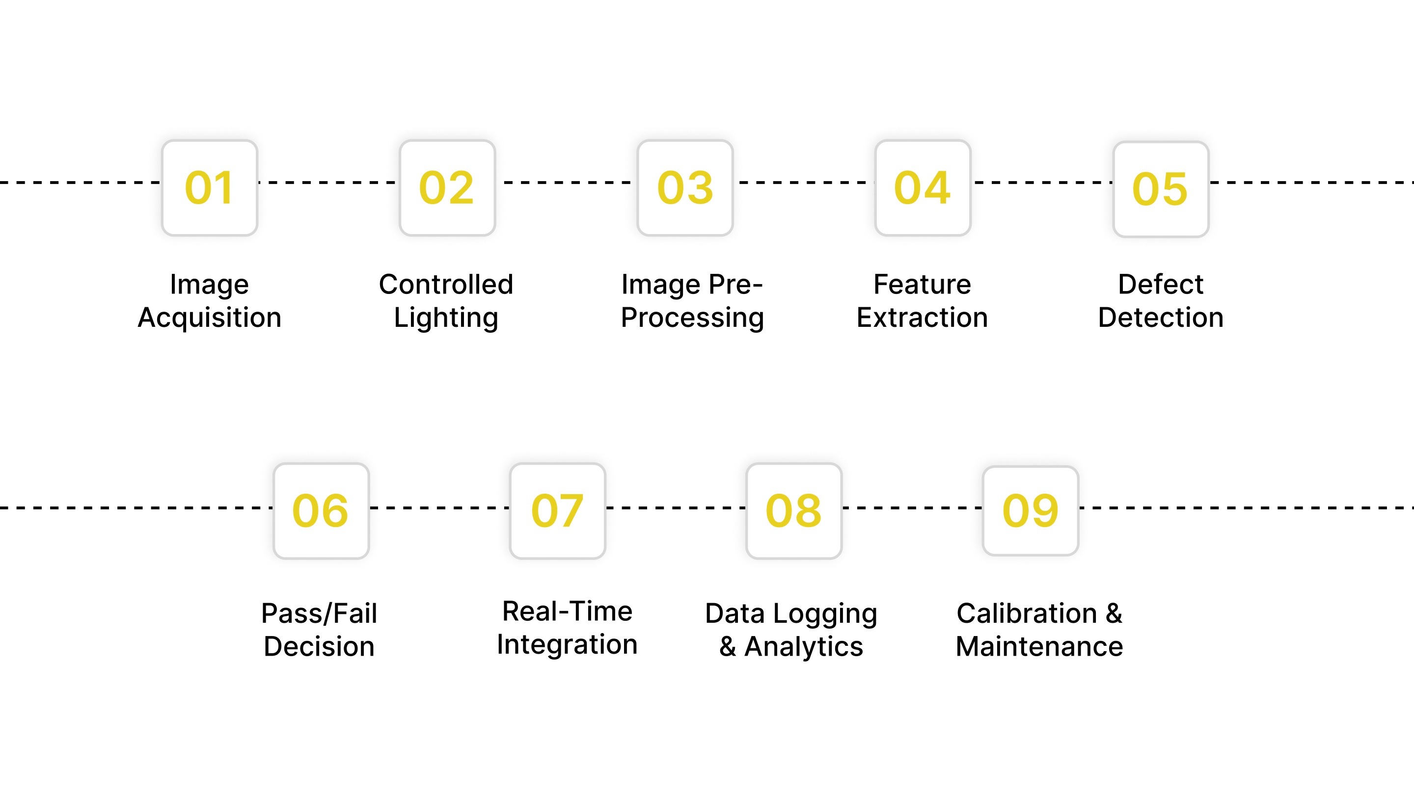
Below is an expanded, technically detailed breakdown of how these systems operate on a modern production line.
1. Image Acquisition (Cameras + Sensors)
The process begins with capturing images or 3D data using industrial-grade sensors. Depending on the application, systems may use:
Camera Types
2D area-scan cameras: For general surface and assembly checks
3D sensors (structured light, laser triangulation, stereo vision): For height, warping, gap/flush, deformation
Line-scan cameras: For continuous web materials (film, sheet metal, paper)
Hyperspectral/multispectral cameras: For material, coating, or chemical variation detection
Typical Performance Metrics
Resolution: 5–25 µm/pixel (high precision), up to 1–2 µm in semiconductor-grade systems
Frame rates: 50–1,000+ fps
Line-scan speeds: 300–1,500 mm/s
3D depth accuracy: 5–20 µm depending on sensor type
High-quality image capture determines the system’s ability to detect subtle defects. Poor data cannot be corrected later by software.
2. Controlled Lighting for Maximum Contrast
Lighting is engineered to ensure defects become visible, consistent, and distinguishable.
Common Lighting Methods
Backlighting: Ideal for silhouette, dimensional, or edge detection
Dome lighting: For curved or glossy surfaces to eliminate hotspots
Low-angle/raking light: Highlights scratches and texture changes
Coaxial (on-axis) lighting: For flat, reflective surfaces
Structured lighting (for 3D): Creates height or deformation patterns
Key Considerations
Lighting uniformity
Intensity stability
Color temperature control
Flicker-free operation
Lighting design often determines whether a defect “pops” in the image or is missed entirely.
3. Image Pre-Processing
Before analysis, the system enhances and normalizes the captured images to remove noise and isolate important features.
Typical Pre-Processing Operations
Noise filtering & smoothing
Contrast enhancement
Sharpening and edge enhancement
Color correction or grayscale normalization
Background subtraction
Geometric distortion correction
Image alignment using fiducials
This stage ensures the dataset is clean and prepared for reliable defect detection.
4. Feature Extraction
The system identifies relevant visual or dimensional characteristics.
Extracted Features May Include:
Edges and corners
Surface texture patterns
Contours and shapes
Weld beads, solder fillets, adhesive lines
Component outlines or presence
3D height maps, point clouds, or depth gradients
Feature extraction forms the foundation for both rule-based and AI-driven inspection.
5. Defect Detection Algorithms
Depending on the application, one or more algorithmic methods are used:
Rule-Based Machine Vision
Thresholding
Blob analysis
Geometric pattern matching
Template matching
OCR and barcode reading
AI / Machine Learning Models
Trained on thousands of “good” and “bad” part images
Learns real-world variation that rule-based systems struggle with
Deep Learning Vision
Best for complex textures (metal grains, fabrics, injection-molded parts)
Excels with reflective, deformable, or variable surfaces
Reduces false positives significantly
Defect Classification Output
Location
Type
Severity
Size
Probability/confidence score
6. Pass/Fail Decision
The system compares detected features to defined tolerances, CAD references, or AI decision thresholds.
The output can be:
Pass
Fail
Borderline / Review Required (for human verification if configured)
This decision is typically executed in under 5–20 milliseconds, ensuring compatibility with high-speed automation.
7. Real-Time Integration With Production Lines
Modern inspection systems integrate tightly with factory automation:
Common Integrations
PLCs (Allen-Bradley, Siemens)
Robotic arms (Fanuc, ABB, KUKA, UR)
Conveyors, feeders, pick-and-place units
MES, SCADA, and ERP systems
Typical Real-Time Actions
Automatically eject defective products
Trigger alarms or stop lines
Send measurement data upstream for process correction
Update digital quality dashboards
This integration turns inspection from a standalone task into a continuous improvement tool.
8. Data Logging & Quality Analytics
Every inspection event can be recorded for traceability.
Data Stored May Include:
Original images and processed overlays
Defect locations and types
Pass/fail decisions
Time stamps
Operator ID (if hybrid inspection)
Machine and batch IDs
Analytics Applications
SPC (Statistical Process Control)
Predictive maintenance
Trend detection (increasing scratches, coating issues)
Supplier quality evaluation
Audit trails for IATF, AS9100, GMP, or FDA compliance
Storage Considerations
High-speed lines can generate 50–300 GB/day, so manufacturers must plan for:
On-edge vs. cloud storage
Image retention policies
Compression and selective capture strategies
Cybersecurity protections
9. Calibration & Maintenance (Frequently Overlooked)
Optical systems require periodic calibration to maintain accuracy:
Routine Tasks
Lens cleaning
Lighting stability checks
Focus recalibration
AI model retraining if parts or materials change
Verification using golden samples
Proper calibration prevents drift and maintains measurement precision.
Types of Optical Defect Inspection Systems
Optical defect inspection systems come in multiple configurations, each designed for specific materials, production speeds, defect types, and environmental conditions. Selecting the right system requires understanding how each technology works and where it excels.
Below is a comprehensive, technically detailed breakdown of the most widely used optical inspection systems in U.S. manufacturing.
System Type | How It Works | Best For (Applications) | Industries |
|---|---|---|---|
2D Vision Systems | Capture high-resolution, flat images of surfaces or assemblies. Use rule-based and AI algorithms for pattern detection, presence/absence checks, and surface analysis. | Label verification, print inspection, scratch detection, assembly checks, and orientation verification. | Packaging, consumer goods, electronics, food & beverage. |
3D Vision Systems | Use structured light, laser triangulation, time-of-flight, or stereo imaging to capture depth, height, and surface topology. Generate point clouds or height maps. | Warping, deformation, gap/flush, weld bead inspection, and dimensional measurement. | Automotive, aerospace, medical devices, and machining. |
Line-Scan Systems | Capture continuous image “slices” as materials move under the camera. Ideal for high-speed webs or long, uniform surfaces. | Continuous materials like metal coils, plastics, film, textiles, paper, and glass sheets. | Packaging film, metals, textiles, battery foils, and printing. |
Hyperspectral / Multispectral Systems | Capture image data across multiple wavelengths beyond visible light. Detects material composition, chemical properties. | Contamination detection, coating consistency, chemical defects, and material uniformity. | Food, pharma, automotive coatings, advanced materials, EV batteries. |
Automated Optical Inspection (AOI) | Uses high-resolution cameras and algorithms to inspect PCB assemblies for micro-defects, missing components, solder issues, and polarity errors. | SMT defects, solder bridges, tombstoning, leads, and polarity checks. | Electronics, semiconductors, telecom. |
Optical Metrology Systems | Provide micron-level dimensional measurement using lasers, interferometry, or structured light. Often used for tight tolerances. | First-article inspection, machining accuracy, and Geometric Dimensioning & Tolerancing (GD&T). | Aerospace machining, automotive components, and medical implants. |
Thermal / Infrared Vision | Detects heat signatures to reveal hidden defects, internal component failures, or seal integrity issues. | Hotspot detection, packaging seal inspection | EV batteries, building materials, electronics, and defense. |
Robotic Vision Systems | Cameras mounted on robotic arms for flexible, multi-angle, or large-part inspection. Supports dynamic positioning. | Large components, curved parts, complex geometries, pick-and-inspect tasks. | Heavy equipment, automotive, aerospace. |
Confocal & Laser Scanning Microscopy (Manufacturing-Grade) | High-precision scanning for micro-surface defects at <1 µm accuracy. | Micro-cracks, micro-scratches, semiconductor wafers, lens inspection. | Semiconductors, optical components, microelectronics. |
Inline Coherent Imaging (ICI) / Optical Coherence Tomography (OCT) | Uses interferometry to measure subsurface structures or layered materials. | Battery cell coatings, multilayer films, and medical device coatings. |
Key Features to Look for in an Optical Inspection System
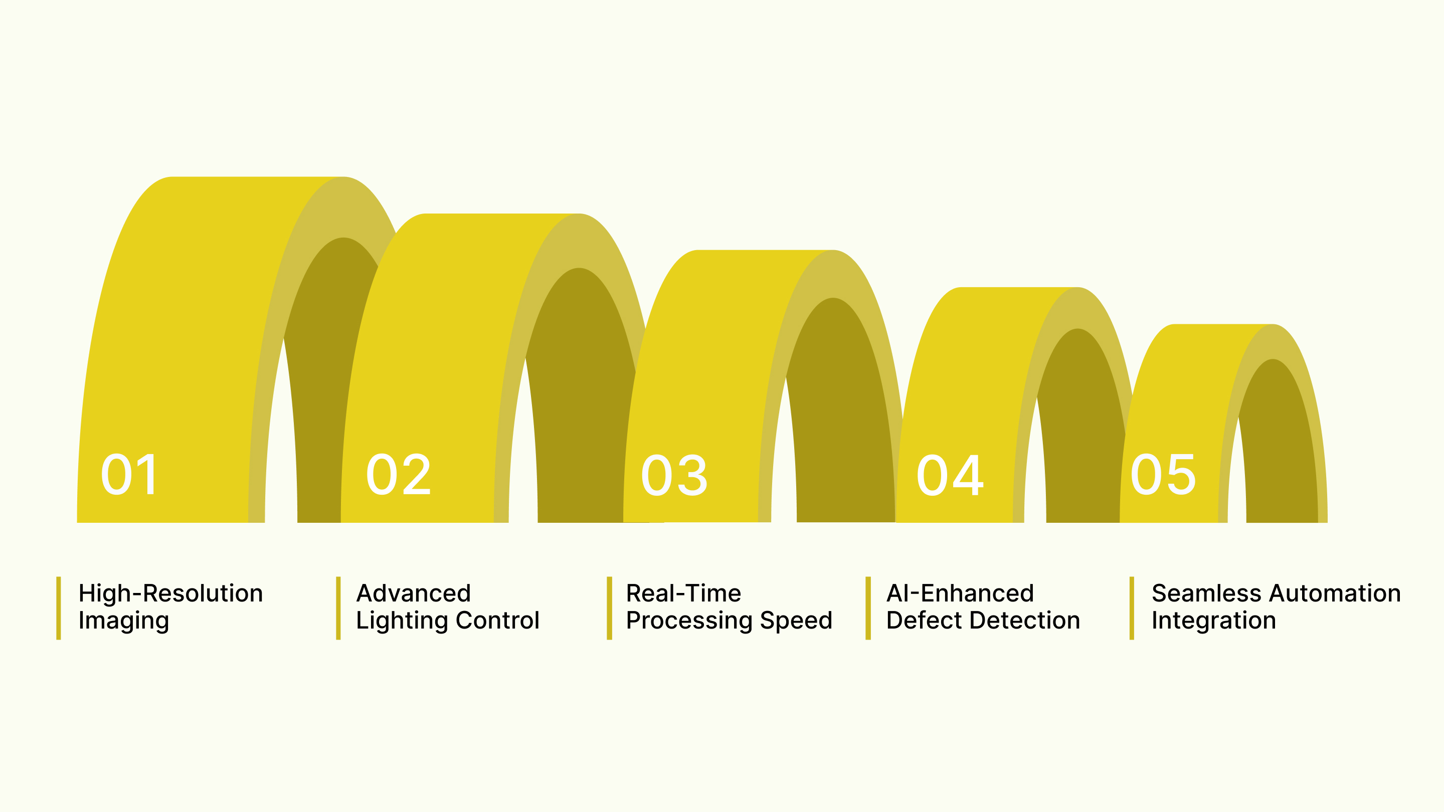
Choosing the right optical defect inspection system requires looking beyond basic camera specifications. A high-quality system should deliver reliability, speed, traceability, and long-term scalability, all essential for modern U.S. manufacturing. Below are the key features decision-makers should prioritize.
High-Resolution Imaging: Choose high-resolution cameras and precision optics to capture micro-defects accurately on fast production lines without compromising inspection clarity or reliability.
Advanced Lighting Control: Use adaptable lighting techniques that enhance contrast, reveal subtle flaws, and ensure consistent visibility across reflective, textured, or transparent materials.
Real-Time Processing Speed: Ensure the system analyzes images instantly, supporting high-throughput manufacturing while maintaining accuracy and reducing bottlenecks in production workflows.
AI-Enhanced Defect Detection: Choose AI-driven detection models that learn defect patterns, minimize false calls, and continuously improve identification accuracy over time.
Seamless Automation Integration: Select platforms that integrate easily with PLCs, robots, MES, and analytics tools to enable traceability, feedback loops, and process optimization.
Conclusion
Optical defect inspection systems have become one of the most reliable and cost-effective tools for achieving consistent, repeatable quality in modern U.S. manufacturing. As product tolerances tighten and regulatory expectations increase, relying solely on manual inspection is no longer sustainable.
By integrating the right optical inspection technology, manufacturers gain precise defect detection, real-time process feedback, and the ability to standardize quality across multiple lines or facilities.
These systems don’t just catch problems; they help prevent them by providing data-driven insights that strengthen upstream processes and long-term product reliability.
Looking for Advanced, High-Precision Optical Inspection Solutions?
Partner with Hammer-IMS, a leader in non-contact, camera-based measurement and defect detection technologies. Explore systems engineered for accuracy, speed, and production-line reliability. Book a demo today.
Frequently Asked Questions (FAQs)
1. What is an optical defect inspection system?
An optical defect inspection system uses cameras, sensors, and imaging algorithms to automatically detect surface defects, dimensional errors, or contamination on products, ensuring consistent, fast, and reliable quality control in manufacturing environments.
2. How accurate are optical inspection systems compared to manual inspection?
Optical systems deliver significantly higher accuracy due to consistent lighting, high-resolution imaging, and automated algorithms, eliminating human fatigue, subjectivity, and variation, especially for small, subtle, or high-speed production defects.
3. What industries benefit most from optical defect inspection?
Industries with strict quality requirements, such as electronics, automotive, aerospace, semiconductors, medical devices, food, and pharmaceuticals, benefit most due to their need for high precision, traceability, and near-zero error rates.
4. Can optical inspection systems detect microscopic or low-contrast defects?
Yes, advanced systems using high-resolution cameras, multi-angle lighting, AI algorithms, and 3D imaging can detect microscopic cracks, scratches and contamination.
5. What factors should be considered before choosing an optical inspection system?
Manufacturers should assess defect size, material type, line speed, lighting conditions, surface reflectivity, integration requirements, scalability, data analytics needs, and future automation goals to ensure the system meets long-term production demands.
6. Can optical inspection replace human inspectors entirely?
Not entirely. Optical inspection automates repetitive, high-speed defect detection, but human inspectors remain essential for complex judgment calls, nuanced visual assessments, and overseeing system performance in specialized or irregular situations.
7. What is needed to maintain an optical inspection system?
Regular calibration, lens cleaning, software updates, lighting checks, and performance validation are essential. Preventive maintenance and periodic alignment ensure accurate detection, consistent output, and long-term reliability in production environments.